Section 2.2. Assembly
2.2. AssemblyLinux is an operating system. As such, sections of it are closely bound to the processor on which it is running. The Linux authors have done a great job of keeping the processor- (or architecture-) specific code to a minimum, striving for the maximum reuse of code across all the supported architectures. In this section, we look at the following:
This section's goal is to cover enough of the basics so you can trace through the architecture-specific kernel code having enough understanding so as not to get lost. We leave advanced assembly-language programming to other books. We also cover some of the trickiest architecture-specific code: inline assembler. To discuss freely PPC and x86 assembly languages, let's look at the architectures of each processor. 2.2.1. PowerPCThe PowerPC is a Reduced Instruction Set Computing (RISC) architecture. The goal of RISC architecture is to improve performance by having a simple instruction set that executes in as few processor cycles as possible. Because they take advantage of the parallel instruction (superscalar) attributes of the hardware, some of these instructions, as we soon see, are far from simple. IBM, Motorola, and Apple jointly defined the PowerPC architecture. Table 2.1 lists the user set of registers for the PowerPC.
Table 2.2 illustrates the Application Binary Interface usage of the general and floating-point registers. Volatile registers are for use any time, dedicated registers have specific assigned uses, and non-volatile registers can be used but must be preserved across function calls.
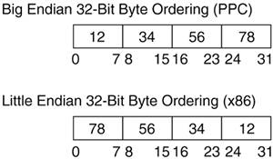
The 32-bit PowerPC architecture uses instructions that are 4 bytes long and word aligned. It operates on byte, half-word, word, and double-word accesses. Instructions are categorized into branch, fixed-point, and floating-point. 2.2.1.1. Branch InstructionsThe condition register (CR) is integral to all branch operations. It is broken down into eight 4-bit fields that can be set explicitly by a move instruction, implicitly, as the result of an instruction, or most common, as the result of a compare instruction. The link register (LR) is used by certain forms of the branch instruction to provide the target address and the return address after a branch. The count register (CTR) holds a loop count decremented by specific branch instructions. The CTR can also hold the target address for certain branch instructions. In addition to the CTR and LR above, PowerPC branch instructions can jump to a relative or absolute address. Using Extended Mnemonics, there are many forms of conditional branches along with the unconditional branch. 2.2.1.2. Fixed-Point InstructionsThe PPC has no computational instructions that modify storage. All work must be brought into one or more of the 32 general-purpose registers (GPRs). Storage access instructions access byte, half-word, word, and double-word data in Big Endian ordering. With Extended Mnemonics, there are many load, store, arithmetic, and logical fixed-point instructions, as well as special instructions to move to/from system registers. 2.2.1.3. Floating-Point InstructionsFloating-point instructions can be broken down into two categories: computational, which includes arithmetic, rounding, conversion, and comparison; and non-computational, which includes move to/from storage or another register. There are 32 general-purpose floating-point registers; each can contain data in double-precision floating-point format.
2.2.2. x86The x86 architecture is a Complex Instruction Set Computing (CISC) architecture. Instructions are variable length, depending on their function. Three kinds of registers exist in the Pentium class x86 architecture: general purpose, segment, and status/control. The basic user set is as follows. Here are the eight general-purpose registers and their conventional uses:
These six segment registers are used in real mode addressing where memory is accessed in blocks. A given byte of memory is then referenced by an offset from this segment (for example, ES:EDI references memory in the ES (extra segment) with an offset of the value in the EDI):
The EFLAGS register indicates processor status after each instruction. This can hold results such as zero, overflow, or carry. The EIP is a dedicated pointer register that indicates an offset to the current instruction to the processor. This is generally used with the code segment register to form a complete address (for example, CS:EIP):
Data ordering in x86 architecture is in Little Endian. Memory access is in byte (8 bit), word (16 bit), double word (32 bit), and quad word (64 bit). Address translation (and its associated registers) is discussed in Chapter 4, but for this section, it should be enough to know the usual registers for code and data instructions in the x86 architecture can be broken down into three categories: control, arithmetic, and data. 2.2.2.1. Control InstructionsControl instructions, similar to branch instructions in PPC, alter program flow. The x86 architecture uses various "jump" instructions and labels to selectively execute code based on the values in the EFLAGS register. Although many variations exist, Table 2.3 has some of the most common uses. The condition codes are set according to the outcome of certain instructions. For example, when the cmp (compare) instruction evaluates two integer operands, it modifies the following flags in the EFLAGS register: OF (overflow), SF (sine flag), ZF (zero flag), PF (parity flag), and CF (carry flag). Thus, if the cmp instruction evaluated two equal operands, the zero flag would be set.
In x86 assembly code, labels consist of a unique name followed by a colon. Labels can be used anywhere in an assembly program and have the same address as the line of code immediately following it. The following code uses a conditional jump and a label: ----------------------------------------------------------------------- 100 pop eax 101 loop2: 102 pop ebx 103 cmp eax, ebx 104 jge loop2 ----------------------------------------------------------------------- Line 100Get the value from the top of the stack and put it in eax. Line 101This is the label named loop2. Line 102Get the value from the top of the stack and put it in ebx. Line 103Compare the values in eax and ebx. Line 104Jump if eax is greater than or equal to ebx. Another method of transferring program control is with the call and ret instructions. Referring to the following line of assembly code: ----------------------------------------------------------------------- call my_routine ----------------------------------------------------------------------- The call instruction transfers program control to the label my_routine, while pushing the address of the instruction immediately following the call instruction on the stack. The ret instruction (executed from within my_routine) then pops the return address and jumps to that location. 2.2.2.2. Arithmetic InstructionsPopular arithmetic instructions include add, sub, imul (integer multiply), idiv (integer divide), and the logical operators and, or, not, and xor. x86 floating-point instructions and their associated registers move beyond the scope of this book. Recent extensions to Intel and AMD architectures, such as MMX, SSE, 3DNow, SIMD, and SSE2/3, greatly enhance math-intensive applications, such as graphics and audio. You are directed to the programming manuals for their respective architectures. 2.2.2.3. Data InstructionsData can be moved between registers, between registers and memory, and from a constant to a register or memory, but not from one memory location to another. Examples of these are as follows: ----------------------------------------------------------------------- 100 mov eax,ebx 101 mov eax,WORD PTR[data3] 102 mov BYTE PTR[char1],al 103 mov eax,0xbeef 104 mov WORD PTR [my_data],0xbeef ----------------------------------------------------------------------- Line 100Move 32 bits of data from ebx to eax. Line 101Move 32 bits of data from memory variable data3 to eax. Line 102Move 8 bits of data from memory variable char1 to al. Line 103Move the constant value 0xbeef to eax. Line 104Move the constant value 0xbeef to the memory variable my_data. As seen in previous examples, push, pop, and the long versions pushl and popl move data to and from the stack (pointed to by SS:ESP). Similar to the mov instruction, the push and pop operations can be used with registers, data, and constants. | |||||||||||||||||||||||||||||||||||||||||||||||||||||||||||||||||||||||||||||||||||||||||||||||||||||||||||||||||
EAN: N/A
Pages: 134