A Business Event Pattern
| Let's start by looking at an example of a requirements pattern. We can then discuss how the pattern was built and how it can be used by future projects. This pattern is based on the response to a business event:
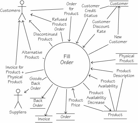
Solution: The following context model, event response model, and class diagram define the pieces of the pattern. Each actor, process, data flow and data store, business object, and association is defined in detail in attached text using the same names as are used in these models. Context of Event ResponseThe context model in Figure 13.4 is a summary of the subject matter covered by the Customer Wants to Buy a Product pattern. You use the diagram to determine whether the details of the pattern might be relevant to the work you are doing. The flows of data (or material) around the boundary of the context indicate the kind of work being done by this pattern. If the majority of these flows are compatible with the inputs and outputs of your event, then the pattern is probably usable in your project. Figure 13.4.This context model defines the boundaries of the pattern Customer Wants to Buy a Product. The arrows identify flows of data and material. All flows coming into the process Fill Order are used by that piece of work to carry out the business rules that produce the flows coming out of Fill Order. Some flows come from or go to adjacent systems such as Suppliers or Customers. Other flows come from or go to stores of information such as Product or Back Order, as indicated by a pair of parallel lines. Of course, this diagram is merely a summary showing the boundaries; the individual requirements are inside the process Fill Order. Once you have decided that the pattern is suitable for your use, it's time to move on to the details. These can be expressed in a number of different ways. The technique that you use depends on the volume and depth of your knowledge about the pattern. For example:
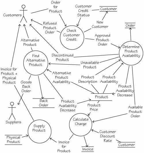
Processing for Event ResponseFigure 13.5 illustrates how a large pattern can be partitioned into a number of subpatterns. From this diagram, we can identify other potentially reusable clusters of requirements. For instance, the diagram has revealed a subpattern called Calculate Charge along with its interactions with other subpatterns. We can use this subpattern independently whenever we want to specify the requirements for calculating any type of charge. The interactions indicate which other patterns might also be relevant to us when we are interested in the pattern for calculating a charge. Other ways of depicting this pattern are to use a UML activity diagram, a sequence diagram, or a scenario. Figure 13.5.This diagram breaks the process Fill Order (shown in Figure 13.4) into five subprocesses (groups of functionally related requirements) and shows the dependencies between them. Each of the subprocesses (shown with a circle) is connected by named data flows to other subprocesses, data stores, or adjacent systems. Each subprocess also contains a number of requirements. Rather than forcing an arbitrary sequence on the processes, this model focuses on the dependencies between the processes. For example, we can see that the process Determine Product Availability has a dependency on the process Check Customer Credit. Why? Because the former needs to know about the Approved Product Order before it can do its work. Data for Event ResponseThe class diagram in Figure 13.6 shows us the objects that participate in the pattern Customer Wants to Buy a Product along with the associations between them. We can cluster the attributes and operations unique to each object. For instance, the object Product has a number of unique attributes, such as its name and price; similarly, it has some unique operations such as calculate discounted price and find stock level. Because we have this cluster of knowledge about the object called Product, whenever we need to specify requirements for a product we can potentially reuse some or all of this knowledge. Figure 13.6.This class diagram shows the objects and associations between them that are part of the pattern Customer Wants to Buy a Product. Consider the business rules communicated by this diagram. A Customer may make zero or many Orders, each of which is invoiced. The Order is for a collection of Order Lines. An Order Line is for a Product, which might be a Service Product or a Goods Product. Only Goods Products can have a Back Order. Now consider how many situations in which these business rules, data, and processes might be reused. Once again, you have many options regarding which models you use to model data. We have used a class model here, but you could just as effectively use an entityrelationship model or any other sort of data model that identifies classes and their associations. |

EAN: 2147483647
Pages: 371