Iterative Refinement
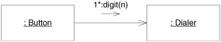
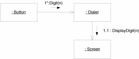
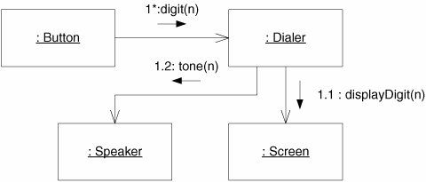
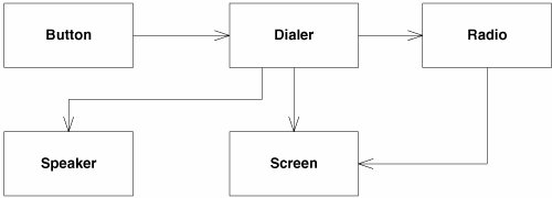
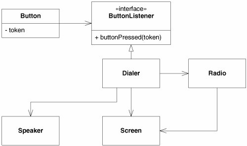
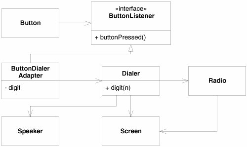
| How do we create UML diagrams? Do we draw them in one brilliant flash of insight? Do we draw the class diagrams first and then the sequence diagrams? Should we scaffold the whole structure of the system before we flesh in any of the details? The answer to all these questions is a resounding no. Anything that humans do well, they do by taking tiny steps and then evaluating what they have done. The things that humans do not do well are things that they do in great leaps. We want to create useful UML diagrams. Therefore, we will create them in tiny steps. Behavior FirstI like to start with behavior. If I think that UML will help me think a problem through, I'll start by drawing a simple sequence diagram or collaboration diagram of the problem. Consider, for example, the software that controls a cellular phone. How does this software make the phone call? We might imagine that the software detects each button press and sends a message to some object that controls dialing. So we'll draw a Button object and a Dialer object and show the Button sending many digit messages to the Dialer (Figure 14-6). (The star means many.) Figure 14-6. A simple sequence diagram What will the Dialer do when it receives a digit message? Well, it needs to get the digit displayed on the screen. So perhaps it'll send displayDigit to the Screen object (Figure 14-7). Figure 14-7. Continuation of Figure 14-6 Next, the Dialer had better cause a tone to be emitted from the speaker. So we'll have it send the tone message to the Speaker object (Figure 14-8). Figure 14-8. Continuation of Figure 14-7 At some point, the user will click the Send button, indicating that the call is to go through. At that point, we'll have to tell the cellular radio to connect to the cellular network and pass along the phone number that was dialed (Figure 14-9). Figure 14-9. Collaboration diagram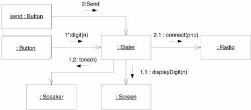 Once the connection has been established, the Radio can tell the Screen to light up the in-use indicator. This message will almost certainly be sent in a different thread of control, which is denoted by the letter in front of the sequence number. The final collaboration diagram is shown in Figure 14-10. Figure 14-10. Cell phone collaboration diagram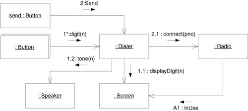 Check the StructureThis little exercise has shown how we build a collaboration from nothing. Note how we invented objects along the way. We didn't know ahead of time that these objects were going to be there; we simply knew that we needed certain things to happen, so we invented objects to do them. But now, before continuing, we need to examine what this collaboration means to the structure of the code. So we'll create a class diagram (Figure 14-11) that supports the collaboration. This class diagram will have a class for each object in the collaboration and an association for each link in the collaboration. Figure 14-11. Cell phone class diagram Those of you familiar with UML will note that we have ignored aggregation and composition. That's intentional. There'll be plenty of time to consider whether any of those relationships apply. What's important to me right now is an analysis of the dependencies. Why should Button depend on Dialer? If you think about this, it's pretty hideous. Consider the implied code: public class Button { private Dialer itsDialer; public Button(Dialer dialer) {itsDialer = dialer;} ... }I don't want the source code of Button mentioning the source code of Dialer. Button is a class that I can use in many different contexts. For example, I'd like to use the Button class to control the on/off switch or the menu button or the other control buttons on the phone. If I bind the Button to the Dialer, I won't be able to reuse the Button code for other purposes. I can fix this by inserting an interface between Button and Dialer, as shown in Figure 14-12. Here, we see that each Button is given a token that identifies it. When it detects that the button has been pressed, the Button class it invokes the buttonPressed method of the ButtonListener interface, passing the token. This breaks the dependence of Button on Dialer and allows Button to be used virtually anywhere that needs to receive button presses. Figure 14-12. Isolating Button from Dialer Note that this change has had no effect on the dynamic diagram in Figure 14-10. The objects are all the same; only the classes have changed. Unfortunately, now we've made Dialer know something about Button. Why should Dialer expect to get its input from ButtonListener? Why should it have a method named buttonPressed within it? What has the Dialer got to do with Button? We can solve this problem, and get rid of all the token nonsense, by using a batch of little adapters (Figure 14-13). The ButtonDialerAdapter implements the ButtonListener interface, receiving the buttonPressed method and sending a digit(n) message to the Dialer. The digit passed to the Dialer is held in the adapter. Figure 14-13. Adapting Buttons to Dialers Envisioning the CodeWe can easily envision the code for the ButtonDialerAdapter. It appears in Listing 14-2. Being able to envision the code is critically important when working with diagrams. We use the diagrams as a shortcut for code, not a replacement for it. If you are drawing diagrams and cannot envision the code that they represent, you are building castles in the air. Stop what you are doing and figure out how to translate it to code. Never let the diagrams become an end unto themselves. You must always be sure that you know what code you are representing. Listing 14-2. ButtonDialerAdapter.cs
Evolution of DiagramsNote that the last change we made in Figure 14-13 has invalidated the dynamic model back in Figure 14-10. The dynamic model knows nothing of the adapters. We'll change that now. Figure 14-14 shows how the diagrams evolve together in an iterative fashion. You start with a little bit of dynamics. Then you explore what those dynamics imply to the static relationships. You alter the static relationships according to the principles of good design. Then you go back and improve the dynamic diagrams. Figure 14-14. Adding adapters to the dynamic model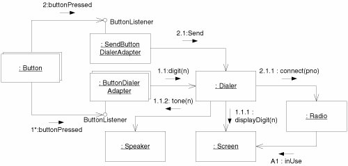 Each of these steps is tiny. We don't want to invest any more than five minutes into a dynamic diagram before exploring the static structure implied. We don't want to spend any more than five minutes refining that static structure before we consider the impact on the dynamic behavior. Rather, we want to evolve the two diagrams together using very short cycles. Remember, we're probably doing this at a whiteboard, and we are probably not recording what we are doing for posterity. We aren't trying to be very formal or very precise. Indeed, the diagrams I have included in the preceding figures are a bit more precise and formal than you would normally have to be. The goal at the whiteboard is not to get all the dots right on your sequence numbers. The goal is to get everybody standing at the board to understand the discussion. The goal is to stop working at the board and start writing code. |
EAN: 2147483647
Pages: 272