Chapter 13. Overview of UML for C Programmers
Chapter 13. Overview of UML for C# Programmers Angela Brooks The Unified Modeling Language (UML) is a graphical notation for drawing diagrams of software concepts. One can use it for drawing diagrams of a problem domain, a proposed software design, or an already completed software implementation. Fowler describes these three levels as conceptual, specification, and implementation.[1] This book deals with the last two.
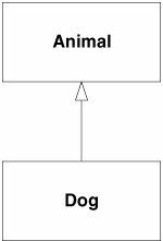
Specification- and implementation-level diagrams have a strong connection to source code. Indeed, it is the intent for a specification-level diagram to be turned into source code. Likewise, it is the intent for an implementation-level diagram to describe existing source code. As such, diagrams at these levels must follow certain rules and semantics. Such diagrams have very little ambiguity and a great deal of formality. On the other hand, diagrams at the conceptual level are not strongly related to source code. Rather, they are related to human language. They are a shorthand used to describe concepts and abstractions that exist in the human problem domain. Since they don't follow strong semantic rules, their meaning can be ambiguous and subject to interpretation. Consider, for example, the following sentence: A dog is an animal. We can create a conceptual UML diagram that represents this sentence, as shown in Figure 13-1. Figure 13-1. Conceptual UML diagram This diagram depicts two entitiesAnimal and Dogconnected by generalization relationship. An Animal is a generalization of a Dog. A Dog is a special case of an Animal. That's all the diagram means. Nothing more can be inferred from it. We might be asserting that our pet dog, Sparky, is an animal; or, we might be asserting that dogs, as a biological species, belong to the animal kingdom. Thus, the diagram is subject to interpretation. However, the same diagram at the specification or implementation level has a much more precise meaning: public class Animal {} public class Dog : Animal {}This source code defines Animal and Dog as classes connected by an inheritance relationship. Whereas the conceptual model says nothing at all about computers, data processing, or programs, the specification model describes part of a program. Unfortunately, the diagrams themselves don't communicate what level they are drawn at. Failure to recognize the level of a diagram is the source of significant miscommunication between programmers and analysts. A conceptual-level diagram does not define source code; nor should it. A specification-level diagram that describes the solution to a problem does not have to look anything like the conceptual-level diagram that describes that problem. All the rest of the diagrams in this book are at the specification/implementation levels and are accompanied by corresponding source code, where feasible. We have seen our last conceptual-level diagram. Following is a very brief tour of the primary diagrams used in UML. Then, you will be able to read and write most of the UML diagrams you will usually need. What remains, and what subsequent chapters address, are the details and formalisms that you will need to become proficient in UML. UML has three main kinds of diagrams. Static diagrams describe the unchanging logical structure of software elements by depicting classes, objects, and data structures and the relationships that exist among them. Dynamic diagrams show how software entities change during execution, depicting the flow of execution, or the way entities change state. Physical diagrams show the unchanging physical structure of software entities, depicting physical entities, such as source files, libraries, binary files, data files, and the like, and the relationships that exist among them. Consider the code in Listing 13-1. This program implements a map based on a simple binary tree algorithm. Familiarize yourself with the code before you consider the diagrams that follow. Listing 13-1. treeMap.cs
|

EAN: 2147483647
Pages: 272