An Example Class Diagram
Figure 19-8 shows a simple class diagram of part of an ATM system. This diagram is interesting both for what it shows and for what it does not show. Note that I have taken pains to mark all the interfaces. I consider it crucial to make sure that my readers know what classes I intend to be interfaces and which I intend to be implemented. For example, the diagram immediately
Figure 19-8. ATM class diagram
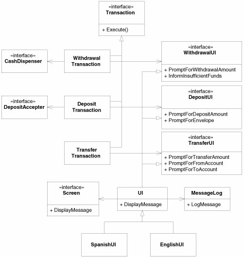
Note that I have not been particularly thorough in documenting the
Again note the convention of horizontal association and vertical inheritance. This helps to differentiate these vastly different kinds of relationships. Without a convention like this, it can be difficult to tease the meaning out of the tangle.
Note how I've separated the diagram into three distinct zones. The transactions and their actions are on the left, the various UI interfaces are all on the right, and the UI implementation is on the bottom. Note also that the connections between the groupings are minimal and regular. In one case, it is three associations, all pointing the same way. In the other case, it is three inheritance relationships, all merged into a single line. The groupings, and the way they are connected, help the reader to see the diagram in
You should be able to see the code as you look at the diagram. Is Listing 19-1 close to what you expected for the implementation of UI? Listing 19-1. UI.cs
|
The DetailsA vast number of details and adornments can be added to UML class diagrams. Most of the time, these details and adornments should not be added. But there are times when they can be helpful. Class Stereotypes
Class stereotypes appear between guillemet
[3]
«interface»
All the methods of classes
Figure 19-9. «interface» class stereotype
I draw interfaces so often that spelling the whole stereotype out at the whiteboard can be pretty inconvenient. So I often use the shorthand in the lower part of Figure 19-9 to make the drawing easier. It's not standard UML, but it's much more
«utility»All the methods and variables of a «utility» class are static. Booch used to call these class utilities . [4] See Figure 19-10.
Figure 19-10. «utility» class stereotype
You can make your own stereotypes, if you like. I often use the stereotypes «persistent », «C-API», «struct», or «function». Just make sure that the people who are reading your diagrams know what your stereotype means. Abstract ClassesIn UML, there are two ways to denote that a class or a method is abstract. You can write the name in italics, or you can use the {abstract} property. Both options are shown in Figure 19-11. Figure 19-11. Abstract classes
It's a little difficult to write italics at a whiteboard, and the {abstract} property is wordy. So at the whiteboard, I use the convention shown in Figure 19-12 if I need to denote a class or method as abstract. Again, this isn't standard UML but at the whiteboard is a lot more convenient. [5]
Figure 19-12. Unofficial denotation of abstract classes
PropertiesProperties, such as {abstract} can be added to any class. They represent extra information that's not usually part of a class. You can create your own properties at any time.
The properties in the
A property that does not have a value is assumed to take the Boolean value true . Thus, {abstract} and {abstract = true} are synonyms. Properties are written below and to the right of the name of the class, as shown in Figure 19-13. Figure 19-13. Properties
Other than the
{abstract}
property, I don't know when you'd find this useful. Personally, in the many
AggregationAggregation is a special form of association that connotes a whole/part relationship. Figure 19-14 shows how it is drawn and implemented. Note that the implementation shown in Figure 19-14 is indistinguishable from association. That's a hint. Figure 19-14. Aggregation
Unfortunately, UML does not provide a strong definition for this relationship. This leads to confusion because various programmers and analysts adopt their own pet definitions for the relationship. For that reason, I don't use the relationship at all, and I recommend that you avoid it as well. In fact, this relationship was almost dropped from UML 2.0. The one hard rule that UML gives us regarding aggregations is simply this: A whole cannot be its own part. Therefore, instances cannot form cycles of aggregations. A single object cannot be an aggregate of itself, two objects cannot be aggregates of each other, three objects cannot form a ring of aggregation, and so on. See Figure 19-15. Figure 19-15. Illegal cycles of aggregation between instances
I don't find this to be a particularly useful definition. How often am I
CompositionComposition is a special form of aggregation, as shown in Figure 19-16. Again, note that the implementation is indistinguishable from association. This time, however, the reason is that the relationship does not have a lot of use in a C# program. C++ programmers, on the other hand, find a lot of use for it. Figure 19-16. Composition
The same rule applies to composition that applied to aggregation. There can be no cycles of instances. An owner cannot be its own ward. However, UML provides quite a bit more definition for composition.
In C#, destruction happens behind the scenes by the garbage collector, so there is seldom a need to manage the lifetime of an object. Deep copies are not unheard of, but the need to show deep-copy semantics on a diagram is rare. So, though I have used composition relationships to describe some C# programs, such use is infrequent. Figure 19-18 shows how composition is used to denote deep copy. We have a class named Address that holds many string s. Each string holds one line of the address. Clearly, when you make a copy of the Address , you want the copy to change independently of the original. Thus, we need to make a deep copy. The composition relationship between the Address and the String s indicates that copies need to be deep. [6]
Figure 19-18. Deep copy
|
|
|
The exact number of elements |
|
|
Zero to many |
|
|
Zero or one, in Java, often implemented with a reference that can be null |
|
|
One to many |
|
|
Three to five |
|
|
Silly, but legal |
Associations can be labeled with stereotypes that change their meaning. Figure 19-20 shows the ones that I use most often.
The «create» stereotype indicates that the target of the association is created by the source. The
The «local» stereotype is used when the source class creates an instance of the target and holds it in a local variable. The implication is that the created instance does not survive the member function that creates it. Thus, it is not held by any instance variable or passed around the system in any way.
The «parameter» stereotype shows that the source class gains access to the target instance though the parameter of one of its member functions. Again, the implication is that the source forgets all about this object once the member function returns. The target is not saved in an instance variable.
Using dashed dependency arrows, as the diagram shows, is a common and convenient idiom for denoting parameters. I usually prefer it to using the «parameter» stereotype.
The «delegate» stereotype is used when the source class forwards a member function invocation to the target. A number of design patterns apply this technique: P ROXY , D ECORATOR , and C OMPOSITE . [7] Since I use these patterns a lot, I find the notation helpful.
[7] [GOF95], pp. 163, 175, 207
Nested classes are represented in UML with an association adorned with a crossed circle, as shown in Figure 19-21.
Associations with multiplicity tell us that the source is connected to many instances of the target, but the diagram doesn't tell us what kind of container class is used. This can be depicted by using an association class, as shown in Figure 19-22.
Association classes show how a particular association is implemented. On the diagram, they appear as a normal class connected to the association with a dashed line. As C# programmers, we interpret this to mean that the source class contains a reference to the association class, which in
Association classes can also be classes that you write in order to hold instances of some other object. Sometimes, these classes enforce business rules. For example, in Figure 19-23, a Company class holds many Employee instances through EmployeeContracts . To be frank, I have never found this notation to be particularly useful.
Association qualifiers are used when the association is implemented through some kind of key or token instead of with a normal C# reference. The example in Figure 19-24 shows a LoginTransaction associated with an Employee . The association is mediated by a member variable named empid, which contains the database key for the Employee .
I find this notation useful in rare situations. Sometimes, it's convenient to show that an object is associated to another through a database or dictionary key. It is important, however, that all the parties reading the diagram know how the qualifier is used to access the object. This is not something that's immediately evident from the notation.