| Models alone can be difficult to pose. They often have too many parts to position properly (such as a tank), or too few (such as a character made from one poly mesh). To help with this issue, animators often build a control structure with which to pose their model. This control structure is referred to as a rig, A rig is usually constructed from joints, curves, and the model itself. Constraints, connections, and parenting are all used to control the behavior of the rig. In a typical rig, geometry is attached to joints, and the motion of those joints is limited through constraints and connections. Additional elements are often brought into the rig, such as NURBS curves. These curves are then linked to the rest of the rig and used by the animator to pose the model. These curves are often referred to as controls. Using controls, you simplify the number of objects you must move to pose the character. Also, since you are not manipulating the joints directly, you can hide the skeleton of the character to avoid accidentally selecting it. One common use of a rig is to automate behavior that you don't wish to animate, such as the movement of machine parts. You can use constraints and connections to ensure accurate driven motion, such as on the wheels of a locomotive. To rig a drive shaft: 1. | From the Front view, create two NURBS or poly wheels, and rotate them so they stand on edge (Figure 10.49).
Figure 10.49. Create two locomotive wheels. Old locomotives are driven by a driveshaft, which is connected to a piston that goes in, out, and around as the wheels rotate. 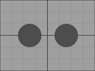
| 2. | Select the Joint tool, and place joints at the top of the right wheel, at the top of the left wheel, and to the left of both wheels.
| | | 3. | Select the Joint tool again, and place a single joint on the axis underneath joint3 (Figure 10.50).
Figure 10.50. Place the joints near the top of each wheel, at the same height. The last joint should rest on the axis a distance away. 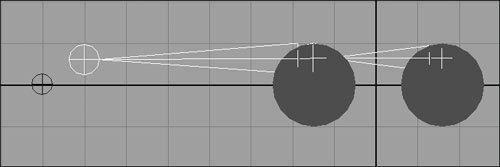
| 4. | Select the right-hand wheel,  -select joint1, and choose the box next to Constrain > Parent. -select joint1, and choose the box next to Constrain > Parent.
The Parent Constraint Options dialog box opens.
| 5. | Make sure that Maintain Offset, Translate All, and Rotate All are selected, and click Apply.
The joint and hierarchy now rotate with the wheel (Figure 10.51).
Figure 10.51. The parent constraint ensures that the first bone in the chain moves with the first wheel. The wheel is shown here rotated away temporarily to illustrate the behavior. 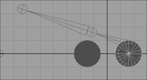
| 6. | Select the left-hand wheel, and -select joint2. In the Parent Constraint Options dialog box, deselect Rotate All, and then click Add (Figure 10.52).
Figure 10.52. An aim constraint drives rotation channels and would conflict with a parent constraint by default. Removing the rotation channels from the parent constraint allows them to be controlled by the aim constraint without conflicting. 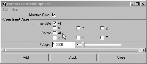
| 7. | Select joint4, -select joint2, and choose Constrain > Aim.
Now, when the left wheel rotates, the drive shaft points at a single goal, whereas joint2 maintains its translation relative to the wheel (Figure 10.53).
Figure 10.53. The left-hand wheel is rotated slightly here. The aim constraint only adjusts rotation; so, the driveshaft bone maintains its length while it always aims toward joint4, where the piston would lie. 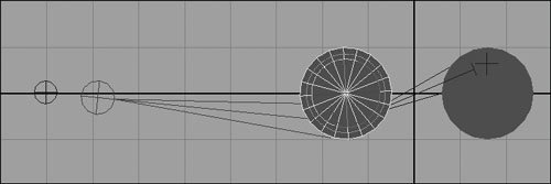
| 8. | Create a NURBS circle for use as a control curve, and position it over the right wheel.
It's usually a good idea to place your control curves in logical places, such as foot controls on the bottom of feet, hip controls around the hips, and so on.
| | | 9. | Select the circle, -select the right wheel, and choose Constrain > Orient.
| 10. | Repeat step 9 for the left wheel.
This binds the orientation of the wheels to that of the circle. Now, when you rotate the circle, the whole drive apparatus moves appropriately (Figure 10.54).
Figure 10.54. Rotating the control rotates the wheels and moves the two shafts all at once. 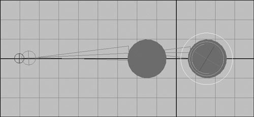
|
 Tip Tip
Character skeletons can become very complex, consisting of hundreds of bones. For instance, the spine of a character may include several bones to ensure a smooth bendbut rotating each bone individually would be time-consuming. Making a spine rig that rotates all the bones at once can save you a lot of time. To rig an FK spine: 1. | Press and hold  to snap the grid, and create six evenly spaced joints pointing up along the y axis (Figure 10.55). to snap the grid, and create six evenly spaced joints pointing up along the y axis (Figure 10.55).
Figure 10.55. Spines should be constructed from the hips up, because the motion of the spine is driven more often from the hips than from the shoulders. 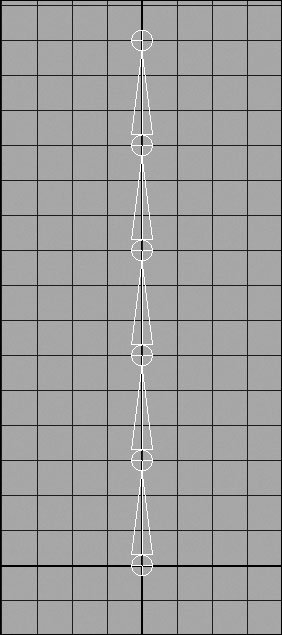
| 2. | Create a NURBS circle, and scale uniformly to 4 units.
Rename this circle Body Control.
| 3. | Create another NURBS circle, rotate it 180 degrees on the y axis, and scale it uniformly to 2 units.
Rename this circle Spine Control.
| 4. | Select Spine Control, -select Body Control, and press  to parent them together (Figure 10.56). to parent them together (Figure 10.56).
Figure 10.56. The controls should be parented together to ensure the Spine Control circle stays at the same location and isn't left behind when the body moves. 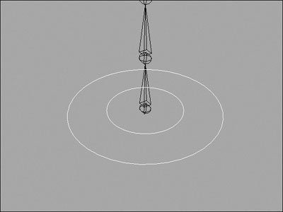
| | | 5. | Choose Window > General Editors > Connection Editor.
The Connection Editor opens.
| 6. | Select the Spine Control circle, and click Reload Left. Then, select joint5 and click Reload Right.
| 7. | Select Rotate Z on the left side and Rotate Z on the right side to link the two (Figure 10.57).
Figure 10.57. Link the Z rotations together. 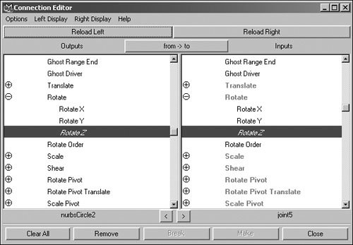
| 8. | On the left side, select Rotate X, and link it to Rotate Y on the right side (Figure 10.58).
Figure 10.58. The local axes of rotation are different for the circle and the bones, so to keep things intuitive, the channels are cross-linked. 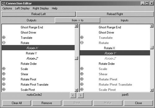
| 9. | Repeat step 8 for joint2, joint3, and joint4.
You only need to reload the right side each time, because the Output side is always the Spine Control circle.
| 10. | Select Spine Control, and rotate it on the x or z axis.
The whole spine bends smoothly (Figure 10.59).
Figure 10.59. With a spine control, only one curve has to be moved to get a smooth rotation from all five joints. 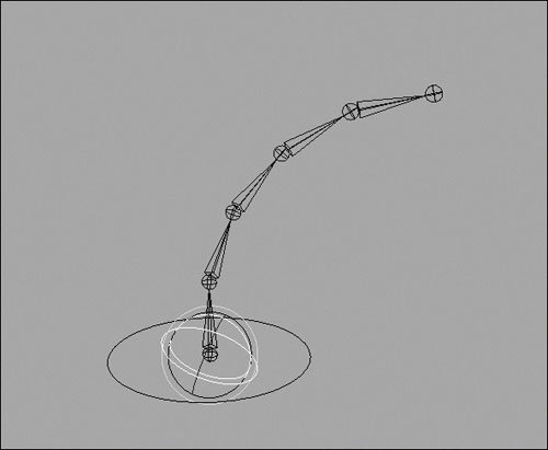
| 11. | Select Body Control, -select joint1, and choose Constrain > Parent.
Be sure the default options are selected.
Now you have a control to move the whole spine and hips of a character, and a control to bend the spine. Notice that Spine Control doesn't bend the hips (joint1) because the rotation of Body Control adjusts them instead.
|
Tip
Legs can be very complicated to rig. The motion of the leg can pivot on the ball of the foot or the heel, and it's important to have control over the placement of the knee. Because the leg is often pinned to the ground, most legs are rigged using IK by default. Doing so allows the foot to be placed easily when animating and lets the rest of the body move without disturbing the feet. To rig an IK leg: 1. | Start with the spine rig from the previous task.
| 2. | Select the Joint tool, click the first joint of the spine (joint1), and construct a five-joint leg (Figure 10.60).
Figure 10.60. Ensure the leg is placed properly in the Front view as well. 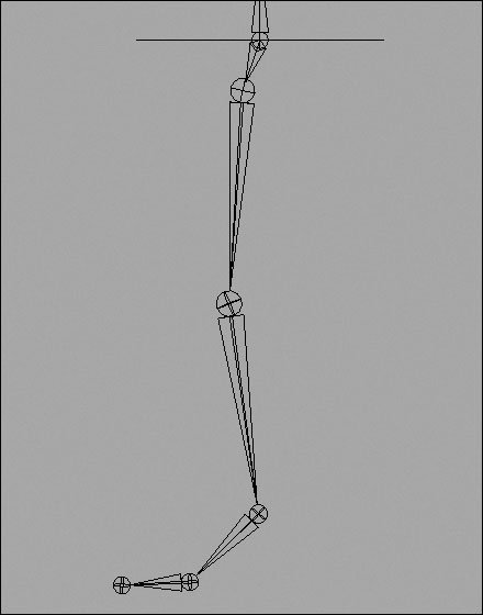
| 3. | Select the IK Handle tool, and add a rotate plane IK handle from the hip to the ankle (Figure 10.61).
Figure 10.61. Because feet often rest on the ground, it's usually best to have legs rigged as IK. 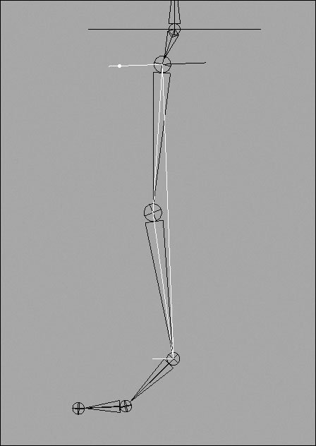
| 4. | Create a NURBS circle, and position it directly under the foot.
Rename this circle Foot Control.
| | | 5. | Create a second circle, and position it in front of the knee (Figure 10.62).
Figure 10.62. Foot Control should be at the bottom of the foot, and Knee Pointer goes directly in front of the knee. 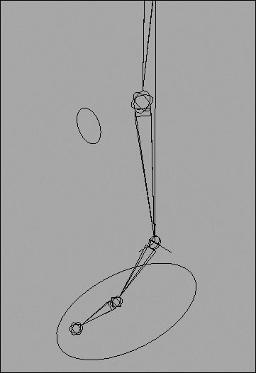
Rename this circle Knee Pointer.
| 6. | Select Knee Pointer, -select Foot Control, and press to parent the pointer to the control.
| 7. | Select the pointer and control, and choose Modify > "Freeze transformations".
This option ensures the controls can easily be returned to their starting locations after animation by setting all transformation values back to zero.
| 8. | Select Foot Control, -select the IK handle, and choose Constrain > Parent.
or
Select them in the reverse order, and press to parent them.
This ensures the ankle translates with the foot control.
| 9. | Select Foot Control, -select the ankle bone, and choose Constrain > Orient (Figure 10.63).
Figure 10.63. The orient constraint ensures the foot stays still unless the control curve is also rotated. 
| | | 10. | Move the foot control around.
The leg follows the control, but there is no control over the placement of the knee.
| 11. | Select Knee Pointer, -select the IK handle, and choose Constrain > Pole Vector (Figure 10.64).
Figure 10.64. Use Knee Pointer to avoid the common IK problem of directing where the solver places the middle joints. 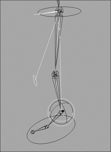
This option lets you aim the knee by moving the pointer. Because Knee Pointer is parented to the foot control, by default the knee rotates with the foot as well (Figure 10.65).
Figure 10.65. In conjunction with the spine, the foot rig now allows independent placement of the hips, knee, ankle, and toe, as well as quick placement of the foot and leg wherever needed. 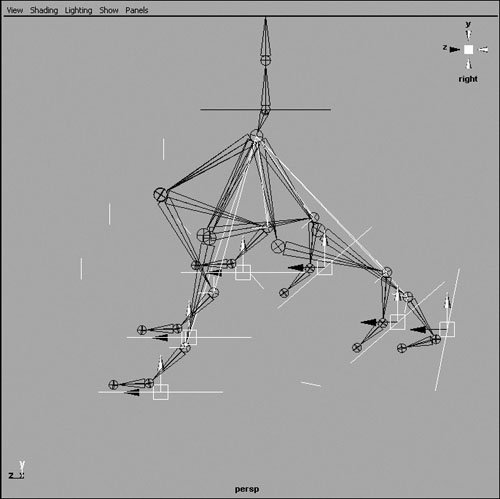
|
About Full Body IK Full Body IK, a new feature in Maya 7.0, is a character rig designed for bipeds and quadrupeds. Full Body IK (FBIK) utilizes pinnable IK handles and a fully interconnected skeleton (Figure 10.66) that makes posing your character quick and easy. Additionally, FBIK automatically adds the complicated set of constraints and connections to your skeleton, saving you from doing it yourself. Figure 10.66. The FBIK skeleton and its accompanying effectors. The circles and boxes around the joints can be used to pin parts of the model in place while posing. 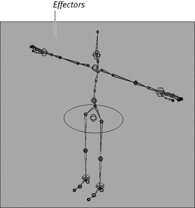
Whereas a normal IK solver only affects a portion of the body, the IK rig of FBIK is entirely interconnected. If you over-extend an IK control, the body adjusts itself to ensure an accurate pose. If you want your character to pick something up, you can drag the hand down to the ground, and the skeleton will bend at the waist and knees to ensure the hand reaches(Figure 10.67). Figure 10.67. FBIK can be a powerful animation tool, giving you quick and precise control over your character. 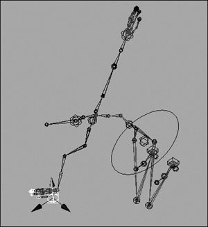
Maya provides a built-in FBIK skeleton that you can use to explore the way FBIK works. To import an example FBIK rig: 1. | Choose Skeleton > Full Body IK > Get FBIK example.
The Visor opens with two models displayed (Figure 10.68).
Figure 10.68. The Visor contains a prerigged biped and quadruped skeleton. 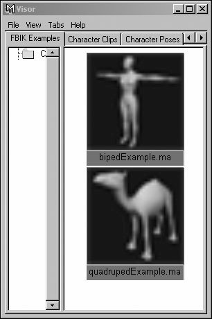
| 2. | With the middle mouse button, drag the example you want into your view.
Now you have an example of FBIK you can bind geometry to or use to explore FBIK options.
|
Setting up for FBIK To use FBIK, you must create a properly named skeleton. FBIK uses the names of your joints to determine what features to add to the rig and where to add them. To create a skeleton for your character, you need to ensure it has a proper hierarchy as well as joints in all the places you need it to bend. To create a skeleton for your character: 1. | Start with the character model you wish to rig (Figure 10.69).
Figure 10.69. If you intend to use FBIK, you should model your character in the appropriate T pose. 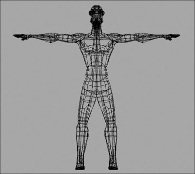
Characters should have their arms out flat, with palms facing straight down.
| | | 2. | From the Side view, and starting at the hips of the character, insert a four-bone spine (Figure 10.70).
Figure 10.70. It generally helps to have the spine follow the curve of the back. Any number of bones may be used. 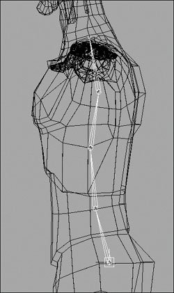
| | | 3. | From the Front view, build a three-bone arm with joints at the shoulder, elbow, wrist and hand (Figure 10.71).
Figure 10.71. The arms should line up from both views, and the bones should face straight away from the body. 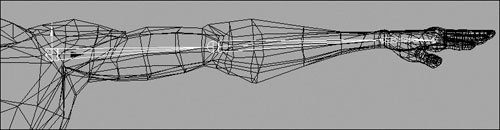
Make sure the bones line up from the Top view as well.
| | | 4. | From the Side view, build a four-bone leg with joints at the hip, knee, ankle and toe (Figure 10.72).
Figure 10.72. Keep the legs straight, and try not to have the knee bend backward; otherwise, the default interpolation may be reversed (and painful looking). 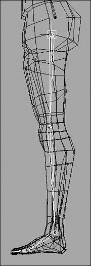
Make sure the bones line up from the Front view as well.
| 5. | Select the hip joint, -select joint1, and then press to parent the leg to the spine (Figure 10.73).
Figure 10.73. When parented correctly, a new bone should appear to connect the two joints. 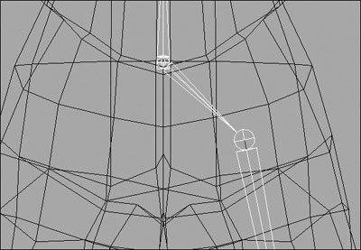
| 6. | Select joint4, -select the shoulder joint, and then press to parent the arm to the spine.
| 7. | Select the shoulder joint, and choose Skeleton > Mirror Joint.
The arm is duplicated on the other side of the body.
| 8. | Select the hip joint, and choose Skeleton > Mirror Joint.
| 9. | Choose Skeleton > Joint Tool. From the Side view, click joint5, and then build a head and neck for your character (Figure 10.74).
Figure 10.74. Everything is mirrored and ready to go. This skeleton contains the bare minimum for an FBIK setup. 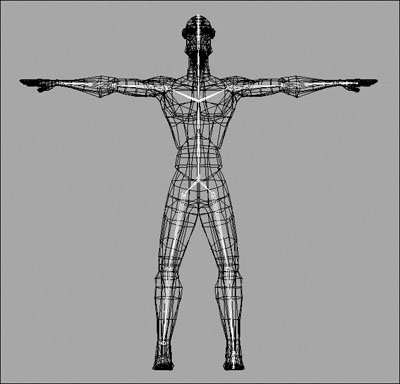
Now you have a skeleton with a suitable hierarchy for FBIK or another type of rig.
|
To label your skeleton: 1. | Start with the skeleton you prepared in the previous task.
| 2. | Select joint1, and choose Skeleton > Joint Labelling > FBIK Labels > Label Root.
The joint is now labeled, but you see no change.
| 3. | Choose Skeleton > Joint Labelling > Show All Labels.
The word Root becomes visible next to the joint you labeled in the previous step (Figure 10.75).
Figure 10.75. Joint labels clearly show the role of each joint as part of the heads up display. 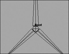
| 4. | One at a time, select the rest of the joints of the spine, and choose Skeleton > Joint Labelling > FBIK Labels > Label Spine (Figure 10.76).
Figure 10.76. Label each spine bone individually, stopping at the neck. 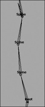
| 5. | Select the shoulder joint, and choose Skeleton > Joint Labelling > FBIK Labels > Label Arm.
The joints are automatically labeled down the arm.
| 6. | With the shoulder still selected, choose Skeleton > Joint Labelling > FBIK Labels > Label Left (Figure 10.77).
Figure 10.77. Labeling the arm saves you the trouble of naming each bone within the arm. 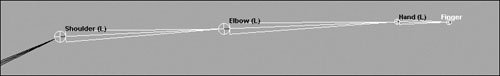
Now the arm is completely labeled, including designations for left and right. Characters are always labeled relative to the character, not how the character is oriented in relation to the user.
| 7. | Select the hip joint, label it Leg, and then label it Left.
| 8. | Repeat steps 5-7 on the right side of the body, labeling the arm and leg Right.
| | | 9. | Select the neck joint or joints, and label them Neck.
| 10. | Select the head joint, and label it Head.
Now your model is fully labeled and ready to rig (Figure 10.78).
Figure 10.78. Once everything is labeled, the rig can be applied. FBIK uses the joint names or labels to build its rig, so double-check for accuracy. 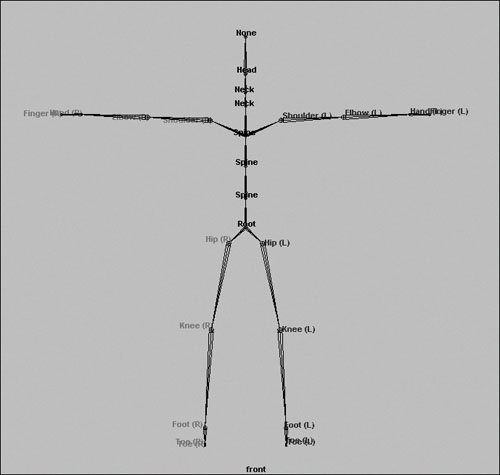
|
Tip To tidy up your joint names, you can choose Skeleton > Joint Labelling > "Rename joints from labels". Doing so gives all your joints names equal to their labels, making it easier to keep track of them.
Using FBIK Once your character is properly prepared, the placement of the rig is entirely automated. Maya creates controls called effectors, which you can position like IK handles to move the character around or pin in space to pose the rest of the character. Effectors can have four states (Figure 10.79): Unpinned Displayed as a sphere, an unpinned effector can be influenced by any other adjustment to the body. Translation ( ). Displayed as a cube, an effector pinned on translation attempts to maintain its position in space, although the joint may still rotate freely. Pinning the translation is useful for a character who is tied at the wrists or who is losing his grip on an object. ). Displayed as a cube, an effector pinned on translation attempts to maintain its position in space, although the joint may still rotate freely. Pinning the translation is useful for a character who is tied at the wrists or who is losing his grip on an object. Rotation ( . Displayed as a half-circle, pinned rotation prevents the joint from rotating relative to its parent. This is useful for a character that who is running while holding something up. . Displayed as a half-circle, pinned rotation prevents the joint from rotating relative to its parent. This is useful for a character that who is running while holding something up. Fully Pinned Displayed as a box with a half-circle under it, a fully pinned control doesn't move at all. This function is effective if you have a character whose hands are gripping or resting on an immovable object.
Figure 10.79. The four different displays for effectors. 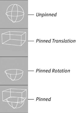
To add FBIK to a skeleton: 1. | Start with the skeleton from the previous task. Select the root joint.
| 2. | Select the option box next to Skeleton > Full Body IK > Add Full Body IK.
| 3. | Ensure that By Label and Biped are selected, and click Apply (Figure 10.80).
Figure 10.80. Set the options you wish to use. 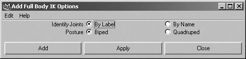
Maya adds the constraints and effectors to your skeleton automatically. Your character is now rigged (Figure 10.81)!
Figure 10.81. The effectors appear on your model in the appropriate spots. Take a moment to double-check that all the effectors you wanted were added, and that they are in the correct places. 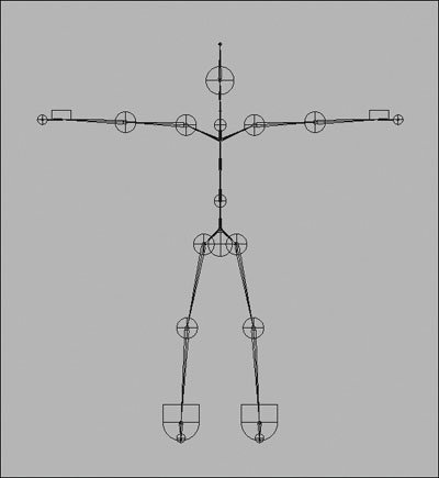
| | | 4. | Select a hand effector, and set Pinning to unpinned in the Channel Box (Figure 10.82).
Figure 10.82. Setting the hand to unpinned frees it to move with the rest of the body. 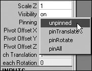
| 5. | Select the other hand, and translate it around in the view.
The rest of the body follows the lead of the hand (Figure 10.83).
Figure 10.83. The body adjusts itself to reach the hand properly. 
| 6. | Select a hand, and press and to pin it in translation and rotation.
| 7. | Drag the body around using the hips effector.
The pinned hand remains in place, as if it's holding on to something (Figure 10.84).
Figure 10.84. Pinning both translation and rotation is ideal for posing characters who are gripping, climbing, or walking. 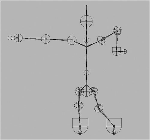
|
|