| Similar to constraints, the Connection Editor is another way to link attributes together. It sets up direct relationships between any two attributes, and you can use the translation values of one object to drive the translation values of another. Although connections can form a broader variety of relationships than constraints, they can't be turned on and off as constraints can. The Connection Editor also supports linking of non-similar attributes. Translation values can be linked to rotations, scale, IK Twist, or any other attribute. This lets you set up powerful control systems for your models (see also "Basic Rigging," later in this chapter). To link two attributes with the Connection Editor: 1. | Create a poly sphere and cube.
| 2. | Choose Window > General Editors > Connection Editor.
The empty Connection Editor window appears (Figure 10.44).
Figure 10.44. The Connection Editor links left-side attributes that control right-side attributes. 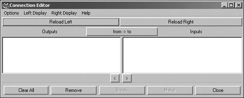
| 3. | Select the sphere, and then click Reload Left.
This loads the sphere's attributes into the Connection Editor. The output, or left side of the editor, controls the connection.
| 4. | Select the cube, and then click Reload Right.
The cube's attributes are loaded into the Connection Editor (Figure 10.45). The input, or right side, is controlled (much like a child object).
Figure 10.45. Both sides are loaded. Many more attributes are displayed here than in the Channel Box. 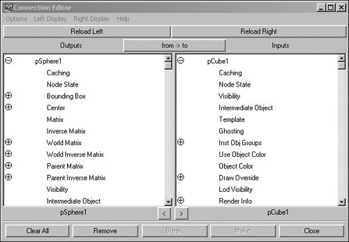
| | | 5. | Scroll down the left side until you find Rotation. Expand it by clicking the plus sign, and then click Rotate X.
The text becomes highlighted in purple, which indicates that you may now connect this attribute to an attribute on the right side (Figure 10.46).
Figure 10.46. Click an attribute on the left side. Connections are always made left to right. 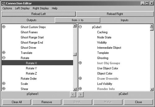
| 6. | Scroll down the right side until you find Translation. Expand this attribute, and then click Translate X.
The attributes become italicized, indicating that they are connected (Figure 10.47).
Figure 10.47. Attributes in italics are currently connected to something. In this case, they are both connected and selected. 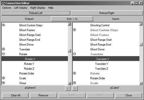
| 7. | Select the sphere in your Perspective view, and rotate it three degrees along the x axis.
The cube moves three units along its x axis (Figure 10.48).
Figure 10.48. With the Connection Editor, you can control any attribute with almost any other attribute. 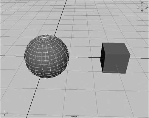
|
 Tips Tips
To remove a connection, select the attribute on the left. Any attributes it's connected to are automatically selected on the right. Then, click the attributes on the right to remove any unwanted connections. You can also connect groups of attributes. To do so, connect any expandable attributes as you would single attributes. Both sides must have the same number of attributes, and unavailable connections are grayed out. You can amplify or reduce the effect of a connection by inserting a multiply node in the Hypergraph. This technique is useful when you're linking attributes that operate on different orders of magnitude, such as rotation to translation. (See Chapter 14, "Shaders, Materials, and Mapping," for more on how to use the Hypergraph.)
|