| You can use nonlinear deformers to quickly distort a surface in a variety of useful ways, greatly speeding tasks that would otherwise require multiple CV selections and transformations. The nonlinear deformers are bend, flare, sine, squash, twist, and wave, each of which alters your surface in a way that matches its name (Figure 13.3). Figure 13.3. Top row, from left to right: Cylinders that have had the bend, flare, sine, and squash deformers applied to them. Bottom row: A cube with a twist deformer applied (left), and a plane with a wave deformer applied (right). 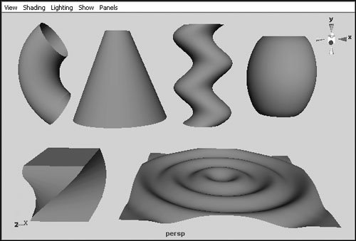
When you create a nonlinear deformer, a special manipulator called a handle is added to your object (Figure 13.4). It's sized to fit your object initially, but if you scale or move the object, the handle doesn't move with it. However, you can select the deformer handle and translate, rotate, or scale it to change its effect on your object (Figure 13.5). Figure 13.4. A deformer handle (highlighted) has been added to this cylinder. 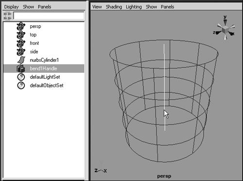
Figure 13.5. Both of these cylinders have had a bend deformer applied to them, but the deformer handle of the cylinder on the right has been rotated 90 degrees. 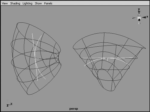
Most of the nonlinear deformer tools have the following options: - Envelope Scales the deformation, not in area, but in the degree to which it affects the surface. The default value is 1, but you can enter values from -2 to 2. A value of 2 doubles the deformation's effect; a negative value inverts the effect.
- Low and High Bound Change where the effect of the deformation begins and ends along the deformation handle. They default to -1 (for low bound) and 1 (for high bound) and can be set to any negative or positive value, respectively.
In addition, each of the nonlinear deformers has its own set of options, which will be covered in the sections that follow. Bend deformer The bend deformer can be a great time saver when you need to bend geometry, but don't want to take the time to move individual CVs or groups of CVs. An additional option for the bend deformer is Curvature, which determines how much the object bends. To use the bend deformer: 1. | Select the object to be deformed.
| 2. | Choose Deform > Create Nonlinear > Bend (Figure 13.6).
Figure 13.6. All of the nonlinear deformers can be created from the Deform > Create Nonlinear menu. 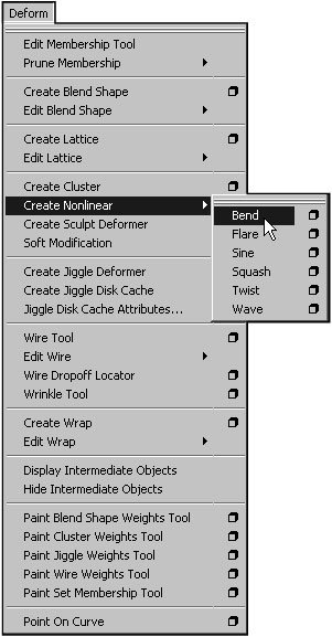
A bend deformer is added to the selected surface.
| 3. | Click the bend1 title under the Inputs section of the Channel Box.
The bend properties are displayed.
| 4. | Set Curvature to 1.
The object is now bent around its center (Figure 13.7).
Figure 13.7. The Curvature attribute of the bend deformer controls the degree of the bend. 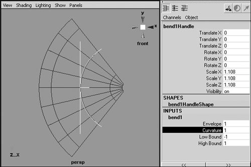
| 5. | Set Low Bound to 0.
The object's bend still starts at its center, but only the top of the object is bent (Figure 13.8).
Figure 13.8. The Low Bound attribute, found in most nonlinear deformers, controls where the deformer's effect begins. 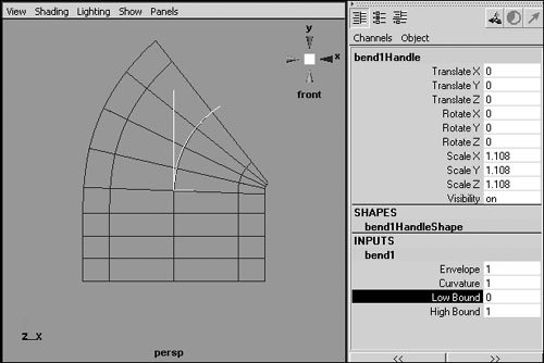
|
 Tip Tip
Flare deformer You can add a flare deformer to a surface to quickly taper or flare its geometry. It's useful for surfaces like jugs, bellies, and bell-bottoms. The additional options for the flare deformer are as follows: Start Flare X and Z Determine the amount of flare at the start of the low bound along the specified axis. End Flare X and Z Determine the amount of flare at the start of the high bound along the specified axis. Curve Determines the amount of curvature between the low and high bound.
To use the flare deformer: 1. | Select the object to be deformed.
| 2. | Choose Deform > Create Nonlinear > Flare.
| 3. | Click the flare1 title under the Inputs section of the Channel Box to view the flare properties (Figure 13.9).
Figure 13.9. When a nonlinear deformer is created, it has no immediate effect on the object. To deform the object, you must change the deformer's properties. 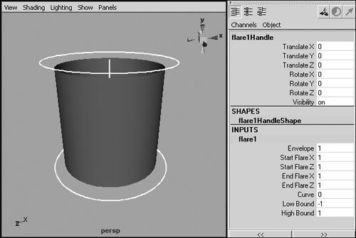
| 4. | Click Start Flare X.
| 5. | Click and drag with the middle mouse button in the view to dynamically change the attribute's value.
or
Type in the desired value.
The object is flared at the bottom along the x axis (Figure 13.10).
Figure 13.10. Adjusting Start Flare X flares the bottom of the object along the x axis. 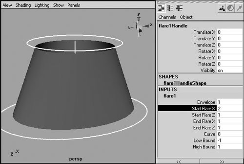
| 6. | Adjust the Curve attribute using one of the methods just described.
The object is curved along the flare (Figure 13.11).
Figure 13.11. Positive values for the Curve attribute create an outward curve along the flare; negative Curve values create an inward curve, as shown here. 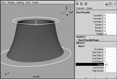
|
Sine deformer The sine deformer changes the shape of an object along a sine wave, which is a line that follows a regular pattern of hills and valleys. The additional sine options are as follows: Amplitude Determines the maximum wave amount. Wavelength Increasing stretches the pattern out over a longer distance. Decreasing this value makes the pattern shorter, creating more repetitions in the same amount of space. Offset Determines the position of the sine wave relative to the center of the deformer handle. Dropoff Determines how the amplitude of the sine wave changes along the deformer handle. Positive values cause the amplitude to get increasingly smaller away from the center of the deformer handle, whereas negative values have the opposite effect.
To use the sine deformer: 1. | Select the object to be deformed.
| 2. | Choose Deform > Create Nonlinear > Sine.
| 3. | Click the sine1 title under the Inputs section of the Channel Box to view the sine properties (Figure 13.12).
Figure 13.12. Be sure your geometry has enough detail to support the deformation you're trying to create. This cylinder of 16 spans will be used to demonstrate the sine deformer. 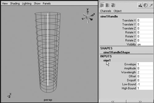
| 4. | Click Amplitude.
| 5. | Click and drag with the middle mouse button in the view, or enter a value in the Amplitude field.
The surface begins to have a wavy shape (Figure 13.13).
Figure 13.13. Amplitude controls the size of the individual sine waves but not their number. 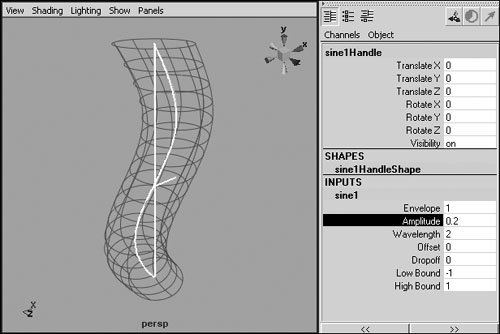
| 6. | Click Wavelength.
| 7. | Click and drag left with the middle mouse button in the view, or enter a smaller value in the Wavelength field.
More waves appear on the surface (Figure 13.14).
Figure 13.14. Reducing the Wavelength value shortens the waves and increases their frequency, creating more of them in a given area. 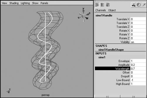
|
Squash deformer The squash deformer lets you both squash and stretch a surface. This differs from scaling the surface along a single axis in that the squash deformer automatically causes the surface to bulge outward when it's squashed or to get thinner as it's stretched. Thus you can maintain the illusion that the surface is a real object with a fixed volume. The additional squash options are as follows: Factor Determines the amount an object is squashed or stretched. Positive values stretch the object, and negative ones squash it. Expand Determines how much an object expands outward while squashing or inward while stretching. Max Expand Position Determines where along the deformer handle the expansion is most prominent. Start and End Smoothness These settings are similar to Dropoff for the sine deformer. These options let you create a smooth transition out of the deformation at their respective ends of the deformation handle.
To use the squash deformer: 1. | Select the object to be deformed.
| 2. | Choose Deform > Create Nonlinear > Squash.
| 3. | Click the squash1 title under the Inputs section of the Channel Box to view the squash properties (Figure 13.15).
Figure 13.15. A bouncing ball is a common application of squash and stretch in animation. 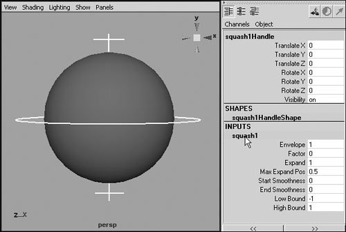
| 4. | Click Factor.
| 5. | Click and drag left and right with the middle mouse button in the view to squash (Figure 13.16)and stretch (Figure 13.17) the object.
Figure 13.16. Using the squash deformer to squash an object automatically bulges the object outward to maintain volume. 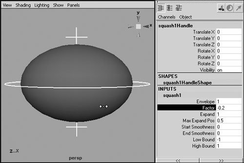
Figure 13.17. Using the squash deformer to stretch an object automatically thins the object to maintain volume. 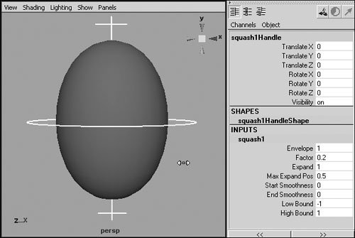
|
Tip
Twist deformer The twist deformer is equivalent to selecting and rotating each cross-section of your geometry to create a smooth twist of a specified number of degrees. However, using a twist deformer is much more efficient than doing this by hand. The twist deformer includes two additional options, Start and End Angle, which determine the degree of twisting at the low or high bound position, respectively. To use the twist deformer: 1. | Select the object to be deformed.
| 2. | Choose Deform > Create Nonlinear > Twist.
| 3. | Click the twist1 title under the Inputs section of the Channel Box to view the twist properties (Figure 13.18).
Figure 13.18. Although you can apply a twist deformer to any surface, its effects are less significant on those with round cross-sections. Here a pyramid is selected. 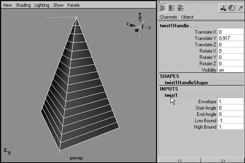
| 4. | Set End Angle to 180.
The surface twists around the center of the deformer such that the top of the object is rotated 180 degrees (Figure 13.19).
Figure 13.19. Changing the Start or End angle twists the surface. 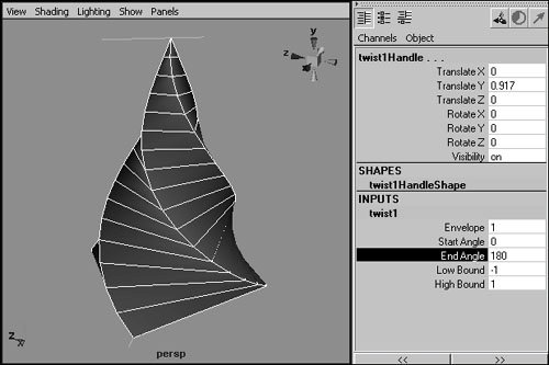
|
Wave deformer The wave deformer is perfect for creating small waves and expanding rings of ripples. This deformer works best on high-resolution flat surfaces. Additional wave options include the following: Amplitude Determines the maximum wave amount. Wavelength Increasing this value makes the waves longer, stretching them out on the surface. Decreasing this value it makes the waves shorter and more frequent. Offset Determines the position of the wave pattern relative to the center of the deformer handle. You can animate the offset to make a surface ripple outward. Dropoff Determines how the amplitude of the waves changes along the deformer handle. Positive values cause the amplitude to get increasingly smaller away from the center of the deformer handle, and negative values have the opposite effect. Dropoff Position Determines where along the deformer handle the Dropoff attribute takes effect. Min and Max Radius Determine where the wave begins and ends along the deformer handle.
To use the wave deformer: 1. | Select the object to be deformed.
| 2. | Choose Deform > Create Nonlinear > Wave.
| 3. | Click the wave1 title under the Inputs section of the Channel Box to view the wave properties (Figure 13.20).
Figure 13.20. The wave deformer works best on flat, detailed surfaces, like this high-resolution plane. 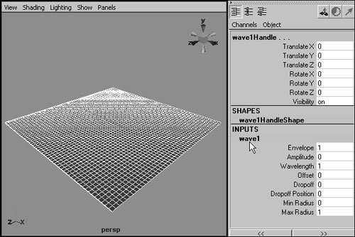
| 4. | Set Amplitude to 0.1.
The object becomes wavy (Figure 13.21).
Figure 13.21. Amplitude controls the height of the individual waves, and Wavelength controls their length. 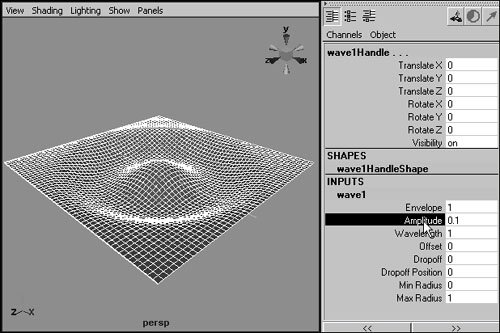
| 5. | Set Wavelength to 0.2.
More waves appear on the object.
| 6. | Set Dropoff to 1.0.
The waves diminish in amplitude away from the center of the object (Figure 13.22).
Figure 13.22. Increasing the Dropoff value causes the amplitude of the waves to decrease as they move away from the center of the object. 
|
|