| The most common way to create a complex polygon model is to start with a primitive poly cube. By transforming this simple object and manipulating its existing components, you can get the basic shape for your model. From there, you can build on the object by adding more complexity to the surface. Polygons include four types of components, which are important for both modeling and texturing: faces, edges, vertices, and UV. - A face is one of the many smaller surfaces that make up the polygon object as a whole. You can choose it by selecting the point in the center of each face (Figure 8.3).
Figure 8.3. The faces are displayed on this sphere. The highlighted face was selected by clicking the dot in the center of the face. 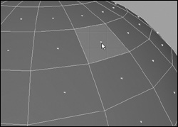
- An edge is one border of a polygonal face (Figure 8.4).
Figure 8.4. The selected edge is shared by the faces on either side of it. Any change to the position or size of this edge will affect all of the faces it touches. 
- A vertex is at the corner of a face. Vertices become yellow when selected (Figure 8.5). If a vertex is moved, it will change the shape of the four faces that include it.
Figure 8.5. The selected vertex is at the corner of four faces. 
- UVs are used for creating texture, not for modeling; they become green when selected (see Chapter 14, "Using Lights").
Two of the most commonly used polygon tools are the Extrude Face tool and the Split Polygon tool. Many other tools are used to manipulate a poly surface, including Extrude Edge and Subdivide.  Tip Tip
Once a face, vertex, or edge is selected, you can move, rotate, or scale the component. For the fastest workflow, use the Marking menu.
To select and transform polygon components: 1. | Create any polygon primitive (see Chapter 3, "Creating Primitives and Text").
| 2. | Right-click a polygon surface to open the Marking menu.
| 3. | From the Marking menu, select Vertex (Figure 8.6).
Figure 8.6. Generally, only one kind of component is displayed at a time. This Marking menu, accessible with the right mouse button, provides a convenient way to switch among the different component displays. 
| 4. | Select some vertices.
You can marquee-select by clicking and dragging (Figure 8.7).
Figure 8.7. Three vertices are selected simultaneously using marquee-select. 
| 5. | Press  or click the Move tool icon or click the Move tool icon  in the toolbar. in the toolbar.
| 6. | Move the vertices (Figure 8.8).
Figure 8.8. The selected vertices are moved using the Move tool. The shape of every face that shares these vertices is changed. 
|
Tips If you are in wireframe mode, you must click a component of the surface, such as an edge, for the Marking menu to show up. If you are in shaded mode, you can click anywhere on the surface. You can use the method described here to select and transform any of the polygon components, except for UVs. You can select UVs in a 3D view, but you can only move them in the UV Texture Editor. For more information on UV textures, see Chapter 15, "Shaders, Materials, and Mapping."
When using polygons, you often work with a large number of components. Maya has several tools to help you select components and to prevent you from selecting components by mistake. These include Backface Culling, which prevents you from picking points on the far side of the object by hiding them, and tools that allow you to grow, shrink, and convert your existing selections. To use Backface Culling: 1. | From the Create menu, select Polygon Primitives > Torus.
| 2. | Right-click a polygon surface to open the Marking menu and select Face.
| 3. | In the Side view, marquee-select the top half of the torus and then delete the faces (Figure 8.9).
Figure 8.9. In the top image, the faces of a torus have been selected in the Side view. (It's often helpful to switch views to get a better angle on your selection.) In the bottom image, you see the torus after the selected faces have been deleted. 
| 4. | From the Display menu, select the box next to Custom Polygon Display.
The Custom Polygon Display Options dialog box opens (Figure 8.10).
Figure 8.10. In the Custom Polygon Display Options dialog box, you can choose whether to have the display options affect all polygon objects or just the selected one(s)for Objects Affected, choose Selected or All. 
| 5. | From the Backface Culling menu, select On and click Apply.
The portions of the torus on the far side of the camera view disappear. They cannot be selected (Figure 8.11).
Figure 8.11. When Backface Culling is turned on, the components on the far side of the object disappear so you can't select them. This feature works for all kinds of polygon components. 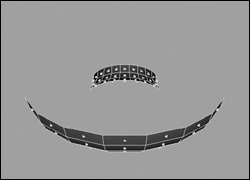
| 6. | From the Backface Culling menu, select Keep Wire. Click Apply.
You can see the wireframe of the back side, but you cannot select components from that part of the surface (Figure 8.12).
Figure 8.12. Backface Culling is set to Keep Wire. This setting allows you to see the shape of the object while preventing you from selecting unwanted components on its back side. 
| 7. | From the Backface Culling menu, select Keep Hard Edges. Click Apply.
You can see the hard edges of the back side onlythat is, the edges along the sides of holes in the surface (Figure 8.13).
Figure 8.13. Keep Hard Edges lets you see the object's basic shape, but only the edges that border a hole in the object. 
| 8. | From the Backface Culling menu, select Off. Click Apply.
The Custom Polygon Display Options are reset to their default values. Now you can select the back sides of polygon surfaces again.
|
To grow, shrink, and convert a selection: 1. | From the Create menu, select Polygon Primitives > Sphere.
| 2. | Right-click a polygon surface and select Vertex from the Marking menu.
| 3. | Select several vertices (Figure 8.14).
Figure 8.14. Several vertices of a polygon sphere are selected. With Backface Culling off, points on the back of the sphere are selected as well. 
| 4. | From the Edit Polygons menu, choose Selection > Grow Selection Region.
The vertices surrounding the existing selection are also selected. Repeat this step to increase the size of the selected area (Figure 8.15).
Figure 8.15. Surgically picking poly vertices one by one can be difficult. One way to save time is to use Edit Polygons > Selection > Grow Selection Region. This selects the points surrounding the ones that are currently selected, making the selected area larger. 
| 5. | From the Edit Polygons menu, choose Selection > Shrink Selection Region.
The region of selected vertices becomes smaller. Repeat this step to further shrink the region.
| 6. | From the Edit Polygons menu, choose Selection > Convert Selection to Faces.
The vertices are deselected, and the faces they surrounded are selected (Figure 8.16).
Figure 8.16. The faces that were surrounded by selected vertices are now selected, and the points are deselected. 
|
Tips A selection of any kind of polygon component can similarly be converted to edges, vertices, or UVs. Some polygon-modeling tools, such as Extrude Face, work only on faces. If you've already selected the region as vertices, Convert Selection saves you the time of meticulously selecting the faces one by one in order to run this tool on the faces.
You can start a model by creating a single face using the Create Polygon tool. To create a polygonal house using the Create Polygon tool: 1. | Select Panels > Orthographic > front to switch to the front orthographic view (Figure 8.17).
Figure 8.17. Switch to the front orthographic view. 
The orthographic view makes it easier to draw a planar face (where all the vertices of the surface fall onto one plane).
| 2. | From the Polygons menu, choose the Create Polygon tool.
The cursor changes to a crosshairs icon, indicating you are ready to create a polygon.
| 3. | In the Front view, click where you want to create the first vertex in the face.
A light green square represents the current vertex.
| 4. | Click and hold to create the next vertex, then drag to see the connection to the previous vertex (Figure 8.18).
Figure 8.18. Place the second vertex in a face using the Create Face tool. 
Tris and Quads For most of your modeling you will want your final polygonal mesh to have three-sided faces (tris) or four-sided faces (quads). Faces can also be planar or non-planar, meaning that the vertices making up the face fall into the same plane. For example, if a playing card is a four-sided polygonal face, it is planar. If you bend it from one corner to the other corner so that it is shaped like a taco, it becomes non-planar. Tris are always planar. Quads can be non-planar, as in the example above, but are appealing for many reasons and can easily be converted to tris. However, when you create n-sided faces with more than four sides, the results can be unpredictable, especially if the face is non-planar or if it is being deformed. For that reason, it's best to avoid n-sided faces. |
| 5. | Release the mouse button to finish the creation of the second vertex.
Once you've created the second vertex, click and drag to see the connection between two vertices.
| 6. | Repeat steps 4 and 5 to create the third vertex (Figure 8.19).
Figure 8.19. Place the third vertex to form a right angle. 
| 7. | Create the fourth vertex and press  (Figure 8.20). (Figure 8.20).
Figure 8.20. Place the fourth vertex to form a square. 
|
This simple polygonal face is the first step in creating any number of models. Now let's add some "windows" to your polygonal house. To make windows for the house: 1. | Follow the previous set of steps to create a four-sided polygonal face.
| 2. | Hold  / / and click inside the face to create a single vertex (Figure 8.21). and click inside the face to create a single vertex (Figure 8.21).
Figure 8.21. Click inside the first face created to begin creating a window. 
| 3. | Create at least three more vertices to create a square hole inside the face (Figure 8.22).
Figure 8.22. Place the fourth vertex in a window using the Create Face tool. 
| 4. | Repeat steps 2 and 3 to create another hole and press .
|
When you build a polygonal model one face at a time, you need to connect those faces together by merging two vertices or edges into one. However, the polygon tools only work on components in the same mesh, so you will have to first combine the separate faces into one mesh. To merge vertices: 1. | Select the surfaces (Figure 8.23) and choose Polygons > Combine. The surfaces are highlighted in one color, indicating that they are one mesh.
Figure 8.23. Select two separate polygon meshes. 
| 2. | Press  to switch to component mode. to switch to component mode.
| 3. | Choose Points  and select a vertex from each face (Figure 8.24). and select a vertex from each face (Figure 8.24).
Figure 8.24. Select two vertices to merge using the Merge Vertices Tool. 
The selected vertices become yellow.
| 4. | From the Edit Polygons menu, select the box next to Merge Vertices.
The Merge Vertex Options dialog box opens (Figure 8.25).
Figure 8.25. Set the Distance to 1 in the Merge Vertex Options dialog box. 
| 5. | In the Merge Vertex Options dialog box, adjust the Distance slider so that it spans the space between the selected vertices (in this case, a value of 1).
| 6. | Click Apply.
The two vertices merge (Figure 8.26).
Figure 8.26. The result of merging two vertices. 
|
To merge edges: 1. | Select the surfaces and choose Polygons > Combine.
The surfaces are highlighted in one color, indicating that they are one mesh.
| 2. | From the Edit Polygons menu, choose Merge Edges tool.
The cursor changes to an arrowhead (Figure 8.27).
Figure 8.27. The cursor changes to an arrowhead when you select the Merge Edge tool. 
| 3. | Click an edge of one of the faces.
The selected edge turns tan, while violet arrow shapes appear on all of the edges that are available for merging (Figure 8.28).
Figure 8.28. The potential target edges have arrows assigned to them. 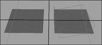
| 4. | Click one of the available edges and press .
The two edges merge (Figure 8.29).
Figure 8.29. The result of merging edges. 
|
When you are editing a mesh, you may need to delete a face. You can simply select and delete most component types of a polygonal mesh, but if you delete a face, it usually leaves a hole. However, the Collapse tool removes the selected faces or edges and then draws the surrounding vertices into a point, without leaving a hole. To collapse the faces of a cube: 1. | From the Create menu, select Polygon Primitives > Cube.
| 2. | Right-click the cube to open a Marking menu and select Face.
| 3. | Click a face on the cube to highlight it (Figure 8.30).
Figure 8.30. Select a face to collapse. 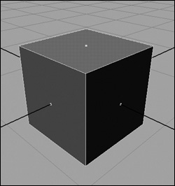
| 4. | Select Edit Polygons > Collapse.
The selected face is removed and the remaining vertices are drawn into a single point (Figure 8.31).
Figure 8.31. The result of collapsing the face. 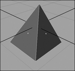
|
When you need to cut a hole out of another polygon, you can use a face to do so in an almost cookie cutter manner, as long as the faces involved belong to the same mesh. To cut a hole in a cube: 1. | From the Create menu, select Polygon Primitives > Cube.
| 2. | From the Create menu, select Polygon Primitives > Plane.
| 3. | Press or click the Move tool icon in the toolbar.
| 4. | Using the Move tool, place the plane above the cube (Figure 8.32).
Figure 8.32. Place a face to use as a hole cutout. 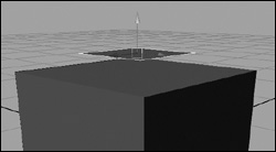
| 5. | Select the cube and the plane and choose Polygons > Combine to combine them into a single mesh.
| 6. | From the Edit Polygons menu, select the Make Hole tool.
The cursor changes to an arrowhead and the mesh switches to face component mode.
| 7. | Click the square in the middle plane to select its face as the shape for the hole (Figure 8.33).
Figure 8.33. Select the face using the Make Hole tool. 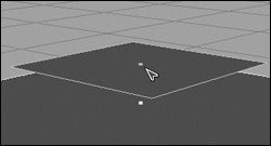
The face becomes highlighted tan.
| 8. | Click the square in the middle of the top of the cube to select its top face as the face from which to cut the hole (Figure 8.34).
Figure 8.34. Select the face from which to cut the hole. 
| 9. | Press to finish making the hole (Figure 8.35).
Figure 8.35. The result of making the hole. 
|
Extrude Face is a great way to begin constructing your surface. It allows you to pull additional geometry from the surface. You simply select a face or faces, extrude them, and then manipulate the new faces. To extrude faces of a cube: 1. | From the Create menu, select Polygon Primitives > Cube.
| 2. | Right-click the cube and select Face from the Marking menu.
| 3. | Marquee-select all of the faces (Figure 8.36).
Figure 8.36. When you use marquee-select around the entire object, even the faces on the far side of the object are selected. 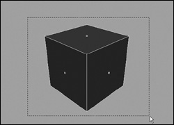
| 4. | From the Edit Polygons menu, select Extrude Face.
A manipulator appears that you can use to move, rotate, and scale the new faces (Figure 8.37). Even though the manipulator shows up on only one face, it affects all of the faces that were just extruded. It transforms them locally, which means that they move relative to their surface normal, which is a line perpendicular to the center of each individual face.
Figure 8.37. This manipulator appears when Edit Polygons > Extrude Face is selected. 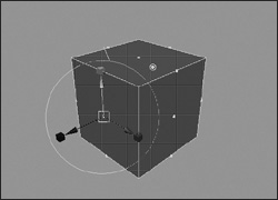
| 5. | Move one face out from the center of the cube with the Translate manipulator.
All newly extruded faces move out from the center as well (Figure 8.38). This procedure is very helpful for creating symmetrical objects.
Figure 8.38. When one face is moved outward, all of the faces move outward. When you scale with the Extrude Face tool, all of the selected faces are scaled simultaneously, relative to their centers. 
|
Tips When you first extrude a face, points appear on the center of each edge of the face you chose (see Figure 8.37). These points remain flat until you move or scale the selected face. Beware any time you see these points along an edge: They can cause problems later in the final rendering because you actually have two surfaces sitting directly on top of each other. To avoid this, make sure that you scale or move a face after every extrusion. After extruding a face, you will often want to scale it proportionally. Simply click any of the scale manipulators, and a proportional scale manipulator will appear in the center. To rotate along a single axis, click the outside rotate manipulator, and three rotate manipulators (one for each axis) will appear. When you extrude more than one face at a time, Maya will extrude those faces separately. To extrude them as one piece, choose Polygons > Tool Options > Keep Faces Together.
To extrude edges: 1. | From the Create menu, select Polygon Primitives > Cube.
| 2. | Right-click the cube and select Face from the Marking menu.
| 3. | Select a face on the side of the cube and press  . .
The face disappears, and you see the inside of the cube (Figure 8.39). (You can also delete an edge or vertex, but this does not make an opening, just a larger face defined by the edges left behind. To try this, pick some vertices and select Delete Vertex from the Edit Polygons menu.)
Figure 8.39. One face of the cube is deleted, creating an opening. 
| 4. | Right-click the cube and select Edge from the Marking menu.
| 5. | Select the left edge and press  to select the right edge of the hole you created (Figure 8.40). to select the right edge of the hole you created (Figure 8.40).
Figure 8.40. The edges on the left and right sides of the opening are selected. 
| 6. | From the Edit Polygons menu, select Extrude Edge.
| 7. | Move the edge out and away from the cube.
Two new faces have been created, and the cube should now look like an open box (Figure 8.41).
Figure 8.41. The edges have been extruded, which creates new faces. When one edge is moved, the other edge moves in the same direction for one axis but in the opposite direction for the other axis (depending on which side of the cube is removed). This figure shows two possible results. 
|
Tip
The Extrude Face and Extrude Edge tools allow you to extrude a selected face or edge along a predefined curve. Setting the number of divisions in the Extrude Face, or Extrude Edge options controls the number of additional polygons added for the extrusion. The higher the Divisions value, the more surface detail and curvature will be added to the final surface. To extrude edges and faces along a path curve: 1. | From the Create menu, select Polygon Primitives > Cube.
| 2. | From the Create menu, select CV Curve Tool.
| 3. | Create a curve that starts near the face or edge you want to extrude and stops where you want the extrusion to end (Figure 8.43).
Figure 8.43. The CV curve is used as an extrusion path for the new surfaces. 
| 4. | Right-click the cube and select Face or Edge from the Marking menu.
| 5. | Select the face or edge you want to extrude along a path (Figure 8.44).
Figure 8.44. The face is selected and ready for extrusion. 
| 6. | Press to select the curve to extrude along.
| 7. | From the Edit Polygons menu, select the box beside Extrude Face if you have a face selected, or Extrude Edge if you have an edge selected.
The Extrude Face or Extrude Edge Options dialog box opens.
| 8. | Make sure that under the Other Values arrow, the Use Selected Curve for Extrusion option is on (Figure 8.45).
Figure 8.45. The Use Selected Curve for Extrusion option is on to ensure that the extruded surfaces follow the path defined by the curve. 
| 9. | Click Apply.
The selected surface component is extruded. By default, only one division is set in the options, so the new surface goes straight from the start point on the surface to the end of the curve (Figure 8.46).
Figure 8.46. Because the Divisions option is set to 1 by default, the resulting surface is a straight extrusion. 
| 10. | With the options dialog box still open, use the middle mouse button to click the program's title bar and then press  to undo the extrusion and keep the component and curve selected. to undo the extrusion and keep the component and curve selected.
| 11. | In the options dialog box under the Other Values arrow, change Divisions to 10 (Figure 8.47).
Figure 8.47. Upping the Divisions setting to 10 gives the final extruded surface enough extra geometry to appear as though it is following along the curve. 
| 12. | Click Extrude Face or Extrude Edge.
The selected face or edge is now extruded along the path curve (Figure 8.48).
Figure 8.48. The selected face is now extruded along the path curve. 
|
Tips
The Extrude Vertex tool is a great addition to the Maya polygon toolset. The Extrude Vertex tool creates additional polygons around the selected vertex in a pyramid-like shape, moving the vertex away from the surface at a user-defined length. To extrude faces from a vertex: 1. | From the Create menu, select Polygon Primitives > Cube.
| 2. | Right-click the cube and select Vertex from the Marking menu.
| 3. | Select the vertex you want to extrude (Figure 8.50).
Figure 8.50. The corner vertex is selected in preparation for the extrusion. 
| 4. | From the Edit Polygons menu, select the box next to Extrude Vertex.
The Extrude Vertex options opens.
| 5. | Set Extrude Length to 2 (Figure 8.51).
Figure 8.51. The Extrude Length setting determines how far the selected vertex will be moved away from the surface. 
The Extrude Length setting determines how far the selected vertex will be moved away from the surface.
| 6. | Click Extrude Vertex.
The vertex is extruded, and additional faces are created to produce a pyramid-like shape (Figure 8.52).
Figure 8.52. A pyramid-like shape is created when the vertex is extruded. 
|
Tips Changing the Extrude Width setting adjusts the percentage of supporting edges used to create the extrusion, making the pyramid-like shape wider. Changing the Divisions setting to a higher number divides the extruded surface into additional polygons (Figure 8.53). Figure 8.53. Divisions is set to 2, creating additional surface geometry on the extrusion. 
The Split Polygon tool is used extensively in polygon modeling and has been improved in recent versions of Maya. It allows you to split one face into two or more faces along an edge that you create. You can split multiple faces simultaneously to save time. Because of the way perspective distorts the view of an object, it can be difficult to select the center of an edge. To help you split a face in the right place, the Split Polygon tool snaps to the center of an edge, or to a user-defined point along an edge. In general, it's best to limit yourself to three- and four-sided faces, known as triangles and quads, respectively. Quads and triangles respond more predictably to other polygon modeling tools. If a face has five or more sides, you should split it into multiple faces with fewer sides each. To split a face: 1. | From the Create menu, select Polygon Primitives > Cube.
| 2. | From the Edit Polygons menu, select the box next to Split Polygon Tool.
The Tool Settings dialog box opens with Split Polygon Tool options.
| 3. | Turn on Snap to Magnets and Snap to Edge and adjust the Magnet Tolerance slider to about the middle of the range (Figure 8.54).
Figure 8.54. The options for the Split Polygon tool make it easy to split a polygon in halves, thirds, quarters, and so on. 
| 4. | Click and drag along a top edge to the center.
The point should snap to the center of the edge (Figure 8.55).
Figure 8.55. Using the Split Polygon tool, you can place a point at the center of an edge. 
| 5. | Release the mouse button.
| 6. | Click and drag along the edge on the opposite side of the top of the cube to the center of that edge (Figure 8.56).
Figure 8.56. The new edge is defined by the two points placed by the Split Polygon tool. Pressing now completes the command. However, you could continue splitting (and go all the way around the cube) by clicking a point on one edge at a time. 
With Snap to Edge set to on, only points along an edge can be selected.
| 7. | Press .
The face is now split in half.
| 8. | Right-click the cube and select Edge from the Marking menu.
| 9. | Select the new edge you created and move it up so that the object looks like a simple house (Figure 8.57).
Figure 8.57. The new edge is moved up, creating a simple house shape. Note that the front of the house has five edges. More than four edges is generally considered bad construction. 
| 10. | From the Edit Polygons menu, select Split Polygon Tool.
| 11. | Click and drag up the left side of the cube until the point snaps to the corner. Repeat for the right side (Figure 8.58).
Figure 8.58. A new edge is created, splitting the front face into two separate faces. 
| 12. | Press .
Now the five-sided face, which formed the front of the house, is split into a three-sided face and a four-sided face.
|
Tips Make sure that your split always creates an edge. If you click one edge and press without successfully clicking another edge of the same face, you will put a vertex on that edgeanother example of bad construction. To avoid this problem, just make sure to undo the action if the Split Polygon tool does not create a new edge. Snapping can make it difficult to create a split where you want. To turn off snapping, under the Split Polygon Tool options in the Tool Settings dialog box, uncheck Snap to Edge. You are not limited to snapping to the middle of an edgeyou can snap to more than one point of an edge. If you want to split a polygon into thirds, snap to a point one-third of the way along an edge. You can enter 2 for Number of Magnets in the Split Polygon Tool options in the Tool Settings dialog box. This creates two points, evenly spaced along the edge, that the tool will snap to (Snap to Magnets must also be selected).
Splitting multiple polygons using the Split Polygon tool can be a tedious process, but the Cut Face tool can cut through a surface like a knife cutting through a block of cheese (Figure 8.59). To be more specific, the Cut Face tool adds edges to a poly (or an entire poly object) through a projected line that you position to your liking (Figure 8.60). The line is projected from the view angle of the camera, slicing through all of the selected intersecting polygons. Figure 8.59. The Cut Face tool is an interactive surface-cutting tool that will either delete one side of the cut surface (shown here), or just slice the surface, leaving you with both sides. 
Figure 8.60. The Cut Face tool can be used to slice a piece of a surface by directing the cutting line into the exact position on the surface where you want the cut made. The short line defines which side of the cutting line will be deleted. 
With the Cut Face delete option selected, one side of the cut object will be deleted. This option is useful if you later want to create an instance of the object or mirror the object to complete it (as you would the head of a character). To slice a surface using the Cut Face tool: 1. | Create a primitive polygon cube and select it.
| 2. | From the Edit Polygons menu, select the box beside Cut Faces.
The Polygon Cut Face Tool Options dialog box opens (Figure 8.61).
Figure 8.61. The Polygon Cut Face Tool Options dialog box provides many commands for cutting the surface in an exact, numeric position, or for interactively placing a cutting line. You can adjust the direction (or the plane) in which the cut is made. 
| 3. | Click Enter Cut Tool.
A line appears that is used as the cutting plane (Figure 8.62).
Figure 8.62. You can move and rotate the cut line until it is perfectly aligned with your cut. 
| 4. | Click and drag the line to position the cutting plane on the surface.
| 5. | Release the mouse to cut the surface (Figure 8.63).
Figure 8.63. The cut line is projected from the selected camera angle to make a cut straight through the surface. 
The line is projected across the object, and cuts are made where it crosses a surface. Notice that no surfaces were deleted, just added.
| 6. | In the Cut Face options, check the box beside Delete the Cut Faces (Figure 8.64).
Figure 8.64. Deleting cut faces removes part of the original surface. 
| 7. | Click Enter Cut Tool and Close.
The mouse icon becomes an arrow.
| 8. | Click and drag the line across a surface to choose another cutting plane.
| 9. | Release the mouse to cut the surface.
The surface on one side of the cutting line is deleted (Figure 8.65).
Figure 8.65. The surface on one side of the cutting line is deleted, leaving only a portion of the original surface. 
|
Tips A short line, perpendicular to the cutting line, appears to show you which side of the line will be deleted (see Figure 8.60). Hold to snap the cutting line horizontally, vertically, or at a 45-degree angle, to make a more precise cut. Both polygonal objects and their components can be cut. When you use the cut tools on selected faces in component mode, only those faces will be cut.
Poke Faces is another Maya tool for speeding up your polygon-modeling workflow. You can use it to subdivide a selected face, adding more detail to your model and more selection points. The Poke Faces tool is similar to Subdivide in that it cuts the selected face into perfect triangles. However, the Poke Faces tool offers several workflow advantages, one of which is that once the surfaces have been divided, you're left with a manipulator to move the new polygons. To poke the face of a polygon using the Poke Faces tool: 1. | Create a primitive polygon cube.
| 2. | Right-click the cube's surface and select Face from the Marking menu.
| 3. | Select one or more faces to poke (Figure 8.66).
Figure 8.66. The selected face is the face that will be split with the Poke command. 
| 4. | From the Edit Polygons menu, select Poke faces.
Each selected face is split into four faces (Figure 8.67).
Figure 8.67. Each selected face is split into four faces, each one a perfect triangle. 
| 5. | Select the manipulator and move it away from the surface.
A pyramid-like shape appears as the manipulator is pulled away from the surface (Figure 8.68).
Figure 8.68. The Poke tool creates a manipulator at the center point of the poked face, which is used to push the new geometry into, or pull it away from, the surface. 
|
The Wedge Face tool is a variation of the Extrude Face tool. It creates angled wedges by extruding selected polygonal faces in an arc (Figure 8.69). This tool is a great time saver when you're creating poly surfaces that will need to be moved and rotated. Figure 8.69. A wedged primitive cube. 
To create a wedge without using the new Wedge Face tool, you would have to extrude the faces of a surface one at a time and then rotate each into position to create the arc shape. You can perform the same task in just a few easy steps using the Wedge Face tool. To wedge the face of a polygon: 1. | Create a primitive polygon cube.
| 2. | Right-click the surface and select Edge from the Marking menu.
| 3. | Select a surface edge that you want the extruded surfaces to curve, or arc, around (Figure 8.70).
Figure 8.70. The selected edge (top-right) defines the wedge's axis rotation point and determines the direction of the extrusion. 
| 4. | Right-click the surface and select Face from the Marking menu.
| 5. | Press to select a face of the same edge (Figure 8.71).
Figure 8.71. The right face of the cube is selected. 
| 6. | From the Edit Polygons menu, select Wedge Faces.
The Polygon Wedge Face Options dialog box opens (Figure 8.72).
Figure 8.72. In the Polygon Wedge Face Options dialog box, you can set the wedge angle and the desired number of wedge divisions for the new surface. 
| 7. | Click Apply.
New geometry is created in an arc around the selected edge, ending 90 degrees from the original selected face (Figure 8.73).
Figure 8.73. New geometry is created in an arc around the selected edge, and additional polygons are created to make the wedge a smoother curve. 
| 8. | Right-click the surface and select Edge from the Marking menu.
| 9. | Select a surface edge of the face on the opposite side of the cube that you want the extruded surfaces to curve, or arc, around (Figure 8.74).
Figure 8.74. Surface edges become important to the Wedge command's rotation and extrusion. Select the edge you want the extrusion to wedge around. 
| 10. | Right-click the surface and select Face from the Marking menu.
| 11. | Press to select a face of the same edge (Figure 8.75).
Figure 8.75. Select the face to be arced. 
| 12. | Change Wedge Angle to 120 and Wedge Divisions to 8; then click Apply.
New geometry is created in an arc around the selected edge, ending 120 degrees from the original selected face and with eight divisions defining the arc (Figure 8.76).
Figure 8.76. You can control the arc amount by changing the Degree attribute. 
|
The Chamfer Vertex tool removes a selected vertex and creates a chamfered corner; a three-sided polygon is created and the original vertex is removed. To chamfer the corner of a polygon: 1. | From the Create menu, select Polygon Primitives > Cube.
| 2. | Right-click the cube and select Vertex from the Marking menu.
| 3. | Select the vertex on the corner you want to chamfer (Figure 8.77).
Figure 8.77. Select a vertex to be chamfered. 
| 4. | From the Edit Polygons menu, select Chamfer Vertex (Figure 8.78).
Figure 8.78. Select Chamfer Vertex to chamfer the selected vertex. 
The corner of the polygon becomes chamfered, creating a three-sided triangle to replace the corner vertex (Figure 8.79).
Figure 8.79. The completed chamfer. 
|
Tips When the Delete Faces option in the Chamfer Vertex options is on, Chamfer Vertex leaves a triangular hole for the chamfered corner, instead of creating a new face. Adjusting the Width option in the Chamfer Vertex options changes the distance down the edges that the chamfer runs, making the newly created triangle wider.
The Bevel tool removes an edge and replaces it with an angled face. Since most real life objects do not have perfectly sharp edges, you'll probably use the Bevel tool a lot. To bevel an edge: 1. | From the Create menu, select Polygon Primitives > Cube.
| 2. | Right-click the cube and select Edge from the Marking menu.
| 3. | On the cube, select the edges you want to bevel (Figure 8.80).
Figure 8.80. Select the edges to be beveled. 
| 4. | From the Edit Polygons menu, select Bevel (Figure 8.81).
Figure 8.81. Select the Bevel command. 
The edges become beveled, creating angled faces (Figure 8.82).
Figure 8.82. The beveled box. 
|
You can also use the Bevel Plus tool to create objects with bevels. Bevel Plus uses curves to extrude objects and give them caps and beveled edges. To create a beveled object with a hole: 1. | Create two closed curves.
For more information on creating NURBS primitives, see Chapter 3.
| 2. | Select the outer curve first and the inner curve(s) next (Figure 8.83).
Figure 8.83. Select the curves you want to bevel. 
| 3. | From the Surfaces menu, select the box next to Bevel Plus.
The Bevel Plus Options dialog box opens (Figure 8.84).
Figure 8.84. Select the Edit Polygons > Bevel command options. 
| 4. | In the Bevel tab, set the Bevel Width and Bevel Depth to 0.1 and the Extrude Distance to 0.25.
| 5. | From the Outer Bevel Style list, select Straight Out.
| 6. | Uncheck the Same as Outer Style check box.
The Inner Bevel Style list becomes active.
| 7. | From the Inner Bevel Style list, select Straight In (Figure 8.85).
Figure 8.85. Select Straight In for the Inner Bevel Style. 
| 8. | In the Output tab, select Polygons.
| 9. | Click Apply to create the beveled object (Figure 8.86).
Figure 8.86. The beveled button. 
|
The Sculpt Polygons tool allows you to manipulate polygon surfaces just as you would work with clay. Unlike the Soft Modification tool, Sculpt Polygons acts more like a brush that pushes and pulls the surface in strokes. To sculpt polygons: 1. | From the Create menu, select the box next to select Polygon Primitives > Plane.
The Plane Options dialog box opens.
| 2. | In the Plane Options dialog box, set the Subdivisons Along Width and Height to 50 and click Apply (Figure 8.87).
Figure 8.87. Set Subdivisions Along Width and Height to 50. 
A dense surface is created (Figure 8.88).
Figure 8.88. Create a dense surface to sculpt. 
| 3. | From the Edit Polygons menu, select the box next to the Sculpt Polygons tool.
The Sculpt Surfaces/Polygons Tool dialog box opens in the Attribute Editor (Figure 8.89).
Figure 8.89. Open the Sculpt Surfaces/Polygons Tool Attribute Editor. 
| 4. | Place the cursor over an active surface.
The cursor turns to a paintbrush icon when the Sculpt Polygons tool is activated and the Sculpt Polygons brush appears when you move the cursor over a selected surface (Figure 8.90).
Figure 8.90. The brush icon and manipulator. The outer circle represents the size of the brush and the arrow represents the direction and amount of the effect. 
| 5. | Hold down  and click and drag to the right to increase the size of the brush, or to the left to decrease its size. and click and drag to the right to increase the size of the brush, or to the left to decrease its size.
| 6. | In the Sculpt Parameters section of the Sculpt Surfaces/Polygons Tool dialog box, use the Max. Displacement slider to change the amount of the effect (Figure 8.91).
Figure 8.91. Set Max. Displacement to .4762 in the Sculpt Parameters section. 
The higher the amount, the more the surface will be displaced. It is usually best to set this value low so that it is easier to control the effect.
| 7. | Check Pull to change the direction of the effect.
Pull displaces the surface towards the brush, whereas Push displaces the surface away from the brush.
| 8. | In the Brush section, choose one of the four Profile shapes to change the shape of the brush (Figure 8.92).
Figure 8.92. Select the second brush profile in the Brush Profiles section. 
| 9. | Drag the brush across the surface to see the effect (Figure 8.93).
Figure 8.93. The sculpted surface. 
|
When modeling, you often create symmetrical objects. Humans, for example, are bi-symmetrical in that one half looks like the other half, but flipped. The Mirror Geometry command will flip one half of an object so you have two symmetrical parts. That means you only have to model one half of a body, then use Mirror Geometry to make a whole person. To mirror geometry: 1. | Select the object to be mirrored (Figure 8.94).
Figure 8.94. Select half of an object. 
| 2. | From the Polygons menu, select the box next to Mirror Geometry.
The Polygon Mirror Options dialog box opens (Figure 8.95).
Figure 8.95. Select +X as the Mirror Direction. 
| 3. | Select a Mirror Direction of +X and click Apply.
The model becomes two halves joined in the middle (Figure 8.96).
Figure 8.96. The symmetrical object. 
|
The Smooth Proxy tool is ideal for situations when you want to work on a low-res model but still want to see how the model will look when it's smoothed or converted to a subdiv surface. Using the Smooth Proxy tool, you can view a smooth version of your low-res model (just as if you had applied the Smooth command to it). The original low-res surface remains visible, allowing you to manipulate fewer points while still viewing the final smoothed shape. When you run the Smooth Proxy command on a polygonal model, Maya creates a new layer that holds the higher-resolution proxy versionconvenient for modeling because you can choose between viewing the low-res and smooth versions simultaneously or individually (by hiding one of the layers). To facilitate surface modeling using the Smooth Proxy tool: 1. | Select a polygonal object in object mode.
| 2. | From the Polygons menu, select Smooth Proxy.
Maya creates a new, smooth version of the model while also retaining the original. Each shape is added to its own layer; you can make one or the other layer invisible to simplify modeling (Figure 8.97).
Figure 8.97. Smooth Proxy allows you to view a smooth version of your model while you work on a lower-res version. In this figure, the low-res version of the model looks like a primitive square; the high-res version looks similar to a sphere. 
| 3. | Right-click the original object and select Vertex from the Marking menu.
| 4. | Select and move one of the vertices.
The high-res version of the model mirrors the manipulations of the low-res model (Figure 8.98).
Figure 8.98. Adjusting the minimal points on the low-res surface adjusts many points on the high-res surface. 
|
Tip
The Subdivide tool splits a face into quads (four-sided faces) or triangles (three-sided faces). It provides a quick way of adding detail to your surface in the form of additional faces. These should not, however, be confused with subdivision surfaces. In this example, we'll combine the Subdivide and Extrude Face tools to create a door. To subdivide a polygon face: 1. | From the Create menu, select Polygon Primitives > Cube.
It's common to start with a cube roughly scaled to the size of an object and then use the Edit Polygon tools to model the surface.
| 2. | Scale the cube to the shape of a door (Figure 8.99).
Figure 8.99. The cube is scaled to the shape of a door. 
| 3. | Right-click the cube and select Face from the Marking menu.
| 4. | Select the face on the front of the cube.
| 5. | From the Edit Polygons menu, select Subdivide.
The face splits into four faces (Figure 8.100).
Figure 8.100. The face is sub-divided into four smaller faces. To subdivide a face into more faces, select Edit Polygons > Subdivide > Options and adjust the Subdivision Levels setting. 
| 6. | From the Edit Polygons menu, select Extrude Face.
The manipulator and new faces appear.
| 7. | Scale the faces down a little using the Manipulator tool (Figure 8.101).
Figure 8.101. The extruded faces are scaled down relative to their centers. 
| 8. | From the Edit Polygons menu, select Extrude Face again.
The manipulator and new faces appear.
| 9. | Scale the new faces down a little and move them in toward the middle of the object, which should now look like a door with four panels (Figure 8.102).
Figure 8.102. A completed four-panel door. Had the face on the opposite side of the door been selected before the Subdivide function, the exact same steps would have modeled the back side of the door simultaneously. 
|
Polygons start out with sharp edges and corners. You can round them by using the Polygons > Smooth function, which sub-divides surfaces into many smaller polygons to round out their corners and edges. To smooth a polygon: 1. | Select a polygon object, such as the door from the previous task.
| 2. | From the Polygons menu, select Smooth.
The Polygon Smooth Options dialog box opens (Figure 8.103). Higher subdivision levels in the Polygon Smooth Options dialog box create smoother objects with more faces. The Continuity setting determines how closely the new shape resembles the original (versus how rounded it is). A low Continuity setting makes the object appear more similar to the original shape; a high Continuity setting produces a very rounded shape.
Figure 8.103. The Polygon Smooth Options dialog box. 
| 3. | Adjust the Subdivision Levels slider to set it to 3.
| 4. | Click Smooth.
The object becomes smooth (Figure 8.104).
Figure 8.104. The original door and the smoother door, side by side. 
|
Tips The basic structure of a polygon object should be complete before you apply the Smooth function. Smoothing produces a dense object with many faces, making it more difficult to work with. You can set Subdivision Levels in the Polygon Smooth Options dialog box as high as 4; however, 3 is generally high enough (and any higher could give you a cumbersome surface due to an abundance of point information). You can change the level of smoothing after the function is complete by clicking polySmoothFace1, which should be at the top of the list of inputs in your Channel Box. You will then see a field labeled Divisions, which you can change from 0 (no smoothing) to 4 (very smooth) (Figure 8.105). Figure 8.105. The inputs in the Channel Box allow you to change the Smooth options after the function has been run. However, once additional tweaks are made to the surface, going back and changing the options in the polySmoothFace input field will produce undesirable results. 
You can smooth a portion of a polygon surface by selecting the faces of the part of the surface you want smoothed and then applying the Smooth operation (Figure 8.106). Figure 8.106. On the left, faces on the top and bottom of the object have been selected. On the right, you see the result of smoothing. The Smooth function works by selecting whole polygon objects or faces of the object; you cannot smooth by selecting vertices or edges. 
The Polygons > Reduce command reduces the number of faces in a selected mesh or subset of a mesh by a user-defined percentage. Keeping the polygon count as low as possible is very important in games and interactive media to keep rendering time to a minimum. The Reduce tool can help achieve this. To reduce the number of faces in a polygonal mesh: 1. | Select the polygon object or the set of faces you want to take polygons away from (Figure 8.107).
Figure 8.107. A poly object with too many polygons. 
| 2. | From the Polygons menu, select Reduce.
The Polygon Reduce Options dialog box opens.
| 3. | Set the Reduce by (%) field to the percentage of polygons by which you want to reduce the mesh80%, for example (Figure 8.108).
Figure 8.108. Set Reduce by (%) to the desired percentage of reduction; here, 80% is used. 
| 4. | Click Reduce.
The polygonal mesh is reduced to 20% of the original number of polygons (Figure 8.109).
Figure 8.109. The poly object now has 80% fewer polygons than before the reduction. 
|
Tip
|