A Campus WLAN Design
|
| < Day Day Up > |
|
Many times, a facility will span more than one building or structure. LAN designers working in multi-building campuses have refined their approach to deploying networks in such situations. They now regularly use structured fiber/UTP wiring systems, a combination of Ethernet switches and routers, and a range of companion devices including firewalls, VPN concentrators, and traffic shapers. And now wireless LAN technology has been added to the mix.
Wireless LANs offer many benefits, but they also make the network designer's and manager's jobs significantly more complex. With conventional wired networks, the design process requires an understanding of how the Physical and Data Link Layers operate in a hybrid switched-routed environment. The designer transfers that understanding to the design of a Physical Layer infrastructure of UTP (unshielded twisted pair) and fiber. The design becomes a bit more complicated, though, when the medium turns invisible and unpredictable. Suddenly, amateur ham radio operators are getting more respect-they understand how radio works. Without that knowledge, it's tough to effectively design a campus WLAN.
If your task is to design a campus WLAN and you don't know much about radio frequency (RF), you need to get up to speed, quickly. Only with a sound understanding of RF can you design the "structured cabling system" of WLANs-an invisible collection of wireless ethers, over which 802.11b packets pass.
To put it more succinctly, when designing a campus WLAN, the designer's challenge is creating a stable cellular communication system with good data throughput campus-wide. This demanding task requires an understanding of how 802.11 radios work, the differences between vendor implementations, and the effect of varying building structure elements and sources of external interference.
You'll also need to think about core network services-including IP address management, authentication, encryption, access control, accounting, and maybe even quality of service that must be delivered to the wireless network's end-users.
Radios
Radio has been around for more than a century. A fluctuating current in a wire is transformed into radio waves and transmitted through the air, where it is received by other radios. With a WLAN, every device is a transceiver, capable of both transmitting and receiving radio signals. By employing any one of a variety of radio modulation schemes- essentially, playing around with the shape of the individual 2.4-GHz sine waves-radio waves can transmit digital information.
Unfortunately, predicting the behavior of a specific WLAN system in a specific environment is challenging. Using identical components, the effective system range may be well over 100 meters (328 feet) in one location and less than 50 meters (164 feet) in another.
A number of variables can affect transmission range, including building layout, construction materials, a warehouse's contents, and noise sources. Experienced WLAN designers can walk into a building, give it a once-over inspection, and make educated guesses about how the system should be designed. For the rest of us, it's trial and error. Fortunately, site survey tools, which are available from most enterprise-oriented vendors, have improved significantly over the past several years. They are a reliable resource when it comes to customizing a WLAN system.
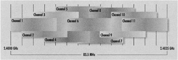
Figure 10.13: Approximate spectral placement of 802.11b channels.
Range Limitations-Friend or Foe
Some people consider the range limitations of radio to be a big problem, but in fact it is the main ally of a wireless system designer. That's because range limitations let you reuse frequencies. As shown in Fig 10.14, designers usually work with channels 1, 6 and 11- three non-overlapping channels-to maximize bandwidth. In other words, a designer could theoretically install three access points (APs) in a room, each transmitting and receiving within a distinct range of frequencies, and with no interference to one another.
While in some rare circumstances, there might be a reason to install three APs in a single room to take advantage of the greater aggregate bandwidth, in most cases there's a different challenge. Assume a building requires 21 APs to deliver service to all users, and seven APs are installed on each of the three non-overlapping channels (1, 6 and 11). The designer needs to ensure not only that cells overlap (to avoid dead spots), but also that an AP on Channel 6 isn't interfering with another access point in the building that's also operating on channel 6. Fig. 10.14 shows a sample cell layout that ensures full coverage while avoiding interference.
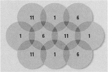
Figure 10.14: This figure shows an 802.11b overlapping cell arrangement using non-overlapping radio channels 1, 6 and 11.
Of course, providing full coverage while avoiding interference is much easier to do on paper than in real life. In the real world, the designer needs to think in three dimensions and factor in the possibility that a cell on the first floor could interfere with a cell on the second floor. This limitation in the number of available channels at 2.4 GHz is one of the primary appeals of 802.11a, which offers eight non-overlapping channels at 5 GHz, though cell diameters usually are smaller.
Designing a Cell Plan
Laying out individual coverage cells takes time. Start with building plans, estimate coverage based on raw distances and workspace configuration, or the mobile employee's pattern of movement in their daily shift. You might, for example, work with 100 foot (30.48 meters) radii, each requiring an AP, and sketch out some locations.
Note that some APs and network interface cards (NICs) can be configured to reduce the output power of the radio, effectively shrinking the RF cell radius and reducing user contention in high-density environments. However, because you can't control the output power on all 802.11b products, a microcell design can get tricky. Unless you are in a position to strictly enforce the wireless devices used on the network, a single rogue device could wreak havoc. Fig. 10.15 shows a microcell design with all APs transmitting at 10 milliwatts. A single client device operating at 100 milliwatts can effectively interfere with multiple cells.

Figure 10.15: Microcell design with interface from a single high-power client.
Now it's time to head into the field, equipped with appropriate tools. Most WLAN vendors offer site survey utilities that let you temporarily install APs and to measure signal levels at various locations. During this phase you are focusing exclusively on the RF design, so you do not need an active Ethernet connection to the AP but you should still use this phase to consider the feasibility of running Ethernet to the various possible AP locations, since it will be an eventual requirement. This is also a good time to consider selecting a product that supports "power over Ethernet" (PoE) to avoid the necessity of providing 110-volt power outlets for each AP.
| Note | Because it's awkward to operate a laptop while moving around, consider using a handheld device, like a PDA when performing the site survey. This type of device makes a great survey tool. The author makes this suggestion even though she does realize that the power and flexibility of the underlying site survey applications for use with PDA operating systems, like Palm and Windows CE, may not be particularly mature. Some professional installers also carry gel-cell DC batteries and DC-to-AC power inverters with them so they can position access points in virtually any location, even if an AC outlet is not nearby. |
Antennae
Another important variable to consider is the type of antenna. Antennae usually provide signal gain by radiating RF signals in a predictable beam pattern. For example, the antennae shipped on most APs are omni-directional, which means that the antenna will transmit a 360 degree beam width roughly in the shape of a doughnut, where the antenna pokes up through the hole in the doughnut. Thus, if you install an AP with an omni-directional antenna in the corner of a building, it will radiate along adjacent hallways as well as out to the parking lot. Also the alignment (polarization) of an omni-directional antenna can affect its transmission pattern, i.e. think about turning the doughnut on end.
Some vendors, including Cisco and Symbol Technologies, offer a variety of antennae for use with their APs. Many of these antennae can provide additional gain-thereby increasing range-by altering the direction and beam width of the radio signal. Patch antennae, for example, can radiate signals using an 80-degree beam width instead of the 360-degree beam width of an omni. Other antennae, like ceiling mounts, are not designed to provide additional gain but rather to blend into the physical environment, with the AP typically concealed above the ceiling.
In designing a campus WLAN, be aware it may not be legal to purchase APs from one company and configure them with third-party antennae. This is because when vendors submit their products for FCC certification, they include an antenna, and it is the combination antenna-AP or antenna-NIC the FCC certifies. So consider purchasing APs from a vendor that provides multiple antenna options.
Beyond RF
Some might argue that the site survey, though technically complex, is the easy part of designing a WLAN. The tougher challenges are assessing and meeting bandwidth requirements, ensuring security, and implementing an appropriate management infrastructure-the same issues LAN designers have wrestled with for years. Address each of these challenges in stages.
First, determine how much bandwidth is needed throughout the physical environment. Pay particular attention to the density of users and typical per-user bandwidth requirements. For example, in a warehouse where only a few users share a vast space, you want to have as large a cell size as possible. Think high-gain antennae. On the other hand, in conference rooms and classrooms where many users must contend for access using the same radio channel. Think smaller cell sizes.
Unfortunately, the number of concurrent users is only one factor driving bandwidth requirements. The other is the bandwidth intensity and relative "burstiness" of the applications. That's not only difficult to estimate at the outset, it's difficult to project. Although if you perform a user-needs analysis as set out in Chapter 14, it will be a bit easier to anticipate these requirements.
In most environments, a single 802.11b channel, which typically provides effective aggregate throughput of about 6 Mbps, can support 30 to 50 users, maybe more. But since in essence, we're back to the old days of shared-media Ethernet, bandwidth monitoring will be important. If specific applications are critical, you may select an AP that allows some level of traffic prioritization. However, third-party products may provide more flexible traffic shaping (though they can add significantly to the cost of the implementation).
Putting It Together
Once you've studied the RF characteristics of the campus, evaluated bandwidth requirements, and laid out your AP-cell design, the next step is to figure out how to integrate the WLAN with the existing wired network. This encompasses both technical and policy dimensions.
On the technical side, you need to develop a security plan and figure out how to tie the access points to the LAN's switching infrastructure, factoring in the management of IP addresses and application roaming requirements. The security strategy should consider authentication, privacy, access control, and accounting. Some WLANs are wide open; others need to meet high security standards. Most of the major vendors, including Cisco, Agere, Proxim and Symbol, offer their own security frameworks that, while based on open standards, may lock you into that specific vendor's APs and NICs. Consider third-party management and security products from vendors like Bluesocket, Columbitech, Ecutel, Funk, NetMotion, NetSeal, ReefEdge, Vernier and others to avoid vendor lock-in. Finally, many organizations use standards-based VPN gateways and VPN clients on all mobile devices to provide a security overlay on their WLANs. There is much more information concerning WLAN security options in Chapter 17.
How you tie APs into your existing network infrastructure will depend on its architecture and the capabilities of the existing Ethernet equipment. For example, with lots of bandwidth and fairly advanced Ethernet switches, you can establish wireless VLANs- maybe even a single wireless VLAN-to manage addresses more easily and to enforce security policies. The wireless VLAN can then be separated logically from the campus wired LAN, and policies can be developed that determine who can cross that boundary. (See the discussion on VLANs in Chapter 8.)
The downside to the campus-wide wireless VLAN design is the same as any flat network: performance may degrade as a result of excessive broadcast traffic. On the positive side, it addresses one of the most challenging aspects of campus WLAN design, how to facilitate roaming users.
With a flat network, users maintain a single IP address. However, when WLANs are associated with IP subnets, roaming is more challenging. If the WLAN's primary need is to provide portability (not mobility), i.e. enabling end-users to move between subnets, it might be reasonable for them to simply restart their machines (or renew their DHCP leases) and get valid IP addresses from their new location. However, if mobility (i.e. walking while remaining connected) is a key requirement for your employees, think about deploying a system that facilitates seamless roaming. NetMotion, for example, serves as a proxy server for all WLAN traffic, thus facilitating roaming. Other solutions include using Mobile IP or customized VPN capabilities to accomplish similar goals. For a detailed discussion on provisioning seamless roaming, see Chapter 7.
|
| < Day Day Up > |
|
EAN: 2147483647
Pages: 273
- ERP System Acquisition: A Process Model and Results From an Austrian Survey
- The Effects of an Enterprise Resource Planning System (ERP) Implementation on Job Characteristics – A Study using the Hackman and Oldham Job Characteristics Model
- Data Mining for Business Process Reengineering
- Healthcare Information: From Administrative to Practice Databases
- Development of Interactive Web Sites to Enhance Police/Community Relations