Case Study: Interface Configuration
|
|
The following case study is designed to simulate a typical JNCIP interface configuration scenario. You will need to refer to the information contained in the lab topology shown in Figure 2.13 and the criteria specified in Table 2.3 for the information needed to complete this case study. It is assumed that you will be applying your interface configuration to the initial system configuration that was performed in Chapter 1, “Initial Configuration and Platform Troubleshooting.”
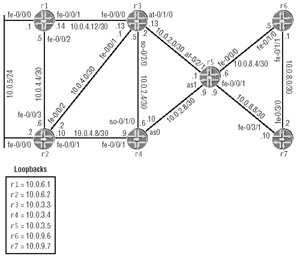
Figure 2.13: Interface case study topology
| Router | Interface | L2 | Logical Unit | Comment |
|---|---|---|---|---|
| r1 | fe-0/0/0 | 150 | — | VRRP group 1, VIP 10.0.5.200, master when link to r3 is up, authenticate with plain-text password jnx |
| fe-0/0/1 | 200 | 200 | VLAN tagging | |
| fe-0/0/2 | — | — | Only accept frames sent from r2’s fe-0/0/3 MAC address | |
| lo0 | — | — | — | |
| r2 | fe-0/0/0 | — | — | VRRP backup for r1 |
| fe-0/0/1 | — | — | Half-duplex | |
| fe-0/0/2 | — | — | — | |
| fe-0/0/3 | — | — | Only accept frames sent from r1’s fe-0/0/2 MAC address | |
| lo0 | — | — | — | |
| r3 | fe-0/0/0 | — | ||
| fe-0/0/1 | — | — | — | |
| so-0/2/0 | 100 | — | Frame Relay, ITU LMI, 15-second polls, 30-millisecond hold-time, threshold/events ratio of 2:3 for line up or down | |
| at-0/1/0 | VP 5 VC 35 | — | 10-second keepalives, link up/down criteria = 2, ILMI-enabled, 50Mbps shaping with no bursts | |
| lo0 | — | — | — | |
| r4 | fe-0/0/1 | — | — | Disable flow control |
| so-0/1/0 | — | — | — | |
| as0 | — | — | SDH framing, path trace set to r4-jnx. Members so-0/1/1 and so-0/1/2 | |
| lo0 | — | — | — | |
| r5 | fe-0/0/0 | — | — | — |
| fe-0/0/1 | — | — | — | |
| at-0/2/1 | — | — | 10-second keepalives, two out of three for link up/down, ILMI-enabled, shaping to 50Mbps with no bursts | |
| as1 | — | — | Path trace set to r5-jnx, members so-0/1/0 and so-0/1/1 | |
| lo0 | — | — | — | |
| r6 | fe-0/1/0 | — | — | — |
| fe-0/1/1 | Device MTU = 4000 | |||
| lo0 | — | — | — | |
| r7 | fe-0/3/0 | — | — | — |
| fe-0/3/1 | — | — | — | |
| lo0 | — | — | — | |
| Entries with “—” are either non-applicable or left to the operator’s discretion. The setting of these parameters may be contingent on the values specified for adjacent router interfaces, so read all details carefully! | ||||
It would seem that you have your work cut out for you, considering that you have seven routers to configure and that each of them can have up to five interfaces with varying requirements. It is expected that a JNCIP candidate will be able to complete this case study in approximately one hour with no mistakes. Sample interface configurations from all seven routers will be provided at the end of the case study for comparison to your own configurations. Some tasks may have multiple solutions, so differences between the provided examples and your own configuration do not automatically indicate that a mistake has been made. In the end, you will be graded on the overall functionality of your configuration and its compliance with any stipulations provided in your configuration task.
Case Study Configurations
The interface-related portions of each router configuration are displayed in Listings 2.2 through 2.8. While these configurations are known to meet the requirements of the case study, other solutions are also possible. Where appropriate, the correct operation of key interface configuration criteria is demonstrated with the appropriate operational mode commands.
Listing 2.2: r1 Interface Configuration
[edit] lab@r1# show interfaces fe-0/0/0 { vlan-tagging; unit 0 { vlan-id 150; family inet { address 10.0.5.1/24 { vrrp-group 1 { virtual-address 10.0.5.200; authentication-type simple; authentication-key "$9$dVw2a5T3nCu"; # SECRET-DATA track { interface fe-0/0/1.200 priority-cost 30; } } } } } } fe-0/0/1 { vlan-tagging; unit 200 { vlan-id 200; family inet { address 10.0.4.14/30; } } } fe-0/0/2 { fastether-options { source-filtering; source-address-filter { 00:a0:c9:6f:70:0d; } } unit 0 { family inet { address 10.0.4.5/30; } } } fxp0 { unit 0 { family inet { address 10.0.1.1/24; } } } lo0 { unit 0 { family inet { address 10.0.6.1/32; } } } The following command verifies that the correct interface is being tracked as part of r1’s VRRP configuration. Forgetting to specify a logical unit, and therefore getting the default value of 0, is a common mistake.
lab@r1> show vrrp track Track if State Cost Interface Group Cfg Run VR State fe-0/0/1.200 up 30 fe-0/0/0.0 1 100 100 master
Listing 2.3: r2 Interface Configuration
[edit] lab@r2# show interfaces fe-0/0/0 { vlan-tagging; unit 0 { vlan-id 150; family inet { address 10.0.5.2/24 { vrrp-group 1 { virtual-address 10.0.5.200; priority 80; authentication-type simple; authentication-key "$9$ZdDHmtpB1hr"; # SECRET-DATA } } } } } fe-0/0/1 { speed 100m; link-mode half-duplex; fastether-options { no-flow-control; } unit 0 { family inet { address 10.0.4.10/30; } } } fe-0/0/2 { unit 0 { family inet { address 10.0.4.2/30; } } } fe-0/0/3 { fastether-options { source-filtering; source-address-filter { 00:a0:c9:6f:7b:84; } } unit 0 { family inet { address 10.0.4.6/30; } } } fxp0 { unit 0 { family inet { address 10.0.1.2/24; } } } lo0 { unit 0 { family inet { address 10.0.6.2/32; } } } The following commands verify VRRP and the overall interface state at r2. The confirmation that r2 is acting as VRRP backup indicates that VRRP has been correctly configured and that authentication is working between r1 and r2 (if r1 and r2 were not communicating, they would both claim mastership of VRRP group 1).
lab@r2> show vrrp summary Interface Unit Group Type Address Int state VR state Fe-0/0/0 0 1 lcl 10.0.5.2 up backup vip 10.0.5.200 lab@r2> show interfaces terse Interface Admin Link Proto Local Remote fxp0 up up fxp0.0 up up inet 10.0.1.2/24 fe-0/0/0 up up fe-0/0/0.0 up up inet 10.0.5.2/24 fe-0/0/1 up up fe-0/0/1.0 up up inet 10.0.4.10/30 fe-0/0/2 up up fe-0/0/2.0 up up inet 10.0.4.2/30 fe-0/0/3 up up fe-0/0/3.0 up up inet 10.0.4.6/30 gre up up ipip up up lo0 up up lo0.0 up up inet 10.0.6.2 --> 0/0 lsi up up pimd up up pime up up tap up up
Listing 2.4 details the interface configuration of r3, which must function as the Frame Relay DTE in order to meet the requirement that it generate a poll every 15 seconds. r3’s DTE appearance requires that r4 be set to function as the DCE to accommodate the LMI keepalive protocol aspects of this case study. r3 also requires SDH framing on its so-0/2/0 interface to be compatible with r4, which in turn must run SDH framing on all of the ports associated with SONET PIC 0/1 to meet the requirements specified for its connection to r5.
Listing 2.4: r3 Interface Configuration
[edit] lab@r3# show chassis fpc 0 { pic 2 { framing sdh; } } alarm { management-ethernet { link-down ignore; } } lab@r3# show interfaces fe-0/0/0 { vlan-tagging; unit 0 { vlan-id 200; family inet { address 10.0.4.13/30; } } } fe-0/0/1 { unit 0 { family inet { address 10.0.4.1/30; } } } at-0/1/0 { atm-options { vpi 0 maximum-vcs 17; vpi 5 maximum-vcs 36; ilmi; } unit 35 { vci 5.35; shaping { cbr 50m; } oam-period 10; oam-liveness { up-count 2; down-count 2; } family inet { address 10.0.2.2/30; } } } so-0/2/0 { hold-time up 30 down 30; encapsulation frame-relay; lmi { n392dte 2; n393dte 3; t391dte 15; lmi-type itu; } unit 100 { dlci 100; family inet { address 10.0.2.5/30; } } } fxp0 { unit 0 { family inet { address 10.0.1.3/24; } } } lo0 { unit 0 { family inet { address 10.0.3.3/32; } } } The following command verifies r3’s Frame Relay interface configuration:
[edit] lab@r3# run show interfaces so-0/2/0 Physical interface: so-0/2/0, Enabled, Physical link is Up Interface index: 16, SNMP ifIndex: 19 Link-level type: Frame-Relay, MTU: 4474, Clocking: Internal, SDH mode, Speed: OC3, Loopback: None, FCS: 16, Payload scrambler: Enabled Device flags : Present Running Interface flags: Point-To-Point SNMP-Traps Link flags : Keepalives DTE ITU LMI settings: n391dte 6, n392dte 2, n393dte 3, t391dte 15 seconds LMI: Input: 248 (00:00:11 ago), Output: 249 (00:00:11 ago) Input rate : 0 bps (0 pps) Output rate : 0 bps (0 pps) SONET alarms : None SONET defects : None Logical interface so-0/2/0.100 (Index 9) (SNMP ifIndex 42) Flags: Point-To-Point SNMP-Traps Encapsulation: FR-NLPID Input packets : 296717 Output packets: 297430 Protocol inet, MTU: 4470, Flags: None Addresses, Flags: Is-Preferred Is-Primary Destination: 10.0.2.4/30, Local: 10.0.2.5 DLCI 100 Flags: Active Total down time: 0 sec, Last down: Never Traffic statistics: Input packets: 296717
One key aspect of r4’s configuration is the need for a t392 timer setting that is greater than the 15-second default. This increase is needed to make r4 compatible with the increased setting of r3’s t391 poll timer. The path trace requirements for r4’s aggregated SONET link to r5 must be specified at the physical SONET device portion of the configuration hierarchy because the as0 device does not support the specification of sonet-options. As shown next in Listing 2.5, r4’s configuration also includes support for SDH framing and the aggregated SONET device setting necessary to support its aso interface.
Listing 2.5: r4 Interface Configuration
[edit] lab@r4# show chassis aggregated-devices { sonet { device-count 1; } } fpc 0 { pic 1 { framing sdh; } } [edit] lab@r4# show interfaces fe-0/0/1 { speed 100m; link-mode half-duplex; fastether-options { no-flow-control; } unit 0 { family inet { address 10.0.4.9/30; } } } so-0/1/0 { dce; hold-time up 30 down 30; encapsulation frame-relay; lmi { n392dce 2; n393dce 3; t392dce 25; lmi-type itu; } unit 100 { dlci 100; family inet { address 10.0.2.6/30; } } } so-0/1/1 { sonet-options { path-trace r4-jnx; aggregate as0; } } so-0/1/2 { sonet-options { path-trace r4-jnx; aggregate as0; } } as0 { aggregated-sonet-options { minimum-links 2; link-speed oc3; } unit 0 { family inet { address 10.0.2.10/30; } } } fxp0 { unit 0 { family inet { address 10.0.1.4/24; } } } lo0 { unit 0 { family inet { address 10.0.3.4/32; } } }
Leaving r4’s t392 at its default setting of 15 seconds is a common mistake, and one that is not readily apparent to the majority of technicians. Having the same setting for the t391 and t392 timers will result in a line that suffers from periodic service outages, which are likely to go unnoticed during your other lab activities. The following syslog entries illustrate typical line bounce frequency for the case where r4 mistakenly uses the default 15-second t392 setting for this case study:
Apr 20 17:01:36 r4 mib2d[578]: SNMP_TRAP_LINK_DOWN: ifIndex 25, ifAdminStatus up(1), ifOperStatus down(2), ifName so-0/1/0 Apr 20 17:03:33 r4 last message repeated 2 times Apr 20 17:12:27 r4 last message repeated 3 times Apr 20 17:22:02 r4 last message repeated 3 times
The configuration of r5 (Listing 2.6) is similar to that of r4 and r3. The tricky part here is the need to set the aggregated device number to a value greater than 1 because of the requirement that it support an as1 device. SDH framing is also needed on r5’s SONET PIC to be compatible with the SDH framing in use on r4’s aggregated so-0/1/1 and so-0/1/2 interfaces. r4 is using SDH framing on these interfaces as a side effect of having to run SDH framing on its so-0/1/0 interface that connects it to r3.
Listing 2.6: r5 Interface Configuration
[edit] lab@r5# show chassis aggregated-devices { sonet { device-count 2; } } fpc 0 { pic 1 { framing sdh; } } [edit] lab@r5# show interfaces fe-0/0/0 { unit 0 { family inet { address 10.0.8.6/30; } } } fe-0/0/1 { unit 0 { family inet { address 10.0.8.9/30; } } } so-0/1/0 { sonet-options { path-trace r5-jnx; aggregate as1; } } so-0/1/1 { sonet-options { path-trace r5-jnx; aggregate as1; } } at-0/2/1 { atm-options { vpi 0 maximum-vcs 17; vpi 5 maximum-vcs 36; ilmi; } unit 35 { vci 5.35; shaping { cbr 50m; } oam-period 10; oam-liveness { up-count 2; down-count 2; } family inet { address 10.0.2.1/30; } } } as1 { aggregated-sonet-options { minimum-links 2; link-speed oc3; } unit 0 { family inet { address 10.0.2.9/30; } } } fxp0 { unit 0 { family inet { address 10.0.1.5/24; } } } lo0 { unit 0 { family inet { address 10.0.3.5/32; } } } The following commands help to verify the operation of r5’s ATM and aggregated interfaces. The support of ILMI requires the declaration of VP 0 because ILMI uses VPI/VCI 0/16.
lab@r5> show interfaces as1 Physical interface: as1, Enabled, Physical link is Up Interface index: 21, SNMP ifIndex: 31 Link-level type: PPP, MTU: 4474, Speed: 311040kbps, Minimum links needed: 2 Device flags : Present Running Interface flags: SNMP-Traps Link flags : Keepalives Keepalive settings: Interval 10 seconds, Up-count 1, Down-count 3 Input rate : 48 bps (0 pps) Output rate : 48 bps (0 pps) Logical interface as1.0 (Index 12) (SNMP ifIndex 33) Flags: Point-To-Point SNMP-Traps Encapsulation: Aggregate Statistics Packets pps Bytes bps Bundle: Input : 424 0 6195 0 Output: 12 0 1056 0 Protocol inet, MTU: 4470, Flags: None Addresses, Flags: Is-Preferred Is-Primary Destination: 10.0.2.8/30, Local: 10.0.2.9
The previous display indicates that the aggregated SONET interface is operational. Now to check on path trace requirements, as shown next:
lab@r5> show interfaces so-0/1/1 extensive | match trace Received path trace: r4-jnx Transmitted path trace: r5-jnx
The path trace settings also appear to be correct. An interesting side effect of configuring r5 with the ability to support two aggregated SONET devices is the automatic creation of an as0 interface. Because this interface is not being used, it is expected to be down, as shown in the following:
lab@r5# run show interfaces terse | match as so-0/1/0.0 up up soagg --> as1.0 so-0/1/1.0 up up soagg --> as1.0 as0 up down as1 up up as1.0 up up inet 10.0.2.9/30
Next we verify the correct operation of r5’s ATM interface:
lab@r5> show interfaces at-0/2/1 Physical interface: at-0/2/1, Enabled, Physical link is Up Interface index: 19, SNMP ifIndex: 27 Link-level type: ATM-PVC, MTU: 4482, Clocking: Internal, SONET mode, Speed: OC3, Loopback: None, Payload scrambler: Enabled Device flags : Present Running Link flags : None Input rate : 0 bps (0 pps) Output rate : 0 bps (0 pps) SONET alarms : None SONET defects : None Logical interface at-0/2/1.35 (Index 8) (SNMP ifIndex 21) Flags: Point-To-Point SNMP-Traps Encapsulation: ATM-SNAP Input packets : 1143 Output packets: 1143 Protocol inet, MTU: 4470, Flags: None Addresses, Flags: Is-Preferred Is-Primary Destination: 10.0.2.0/30, Local: 10.0.2.1 VCI 5.35 Flags: Active, OAM, Shaping CBR, Peak: 50mbps OAM, Period 10 sec, Up count: 2, Down count: 2 Total down time: 0 sec, Last down: Never OAM F5 cell statistics: Total received: 1142, Total sent: 1142 Loopback received: 1142, Loopback sent: 1142 RDI received: 0, RDI sent: 0 AIS received: 0 Traffic statistics: Input packets: 1143 Output packets: 1143 Logical interface at-0/2/1.32767 (Index 9) (SNMP ifIndex 20) Flags: Point-To-Point SNMP-Traps Encapsulation: ATM-VCMUX Input packets : 2 Output packets: 2 VCI 0.16 Flags: Active, ILMI Total down time: 0 sec, Last down: Never Traffic statistics: Input packets: 2 Output packets: 2
The ATM interface status display indicates that all requirements have been met, and that the interface is operating normally.
There is little to note in the interface configurations for r6 and r7 (Listings 2.7 and 2.8), except the need for Jumbo frame support on the r6-r7 Fast Ethernet link. Though it is only specified for r6, r7 must also have a compatible device MTU set for proper operation with r6.
Listing 2.7: r6 Interface Configuration
[edit] lab@r6# show interfaces fe-0/1/0 { unit 0 { family inet { address 10.0.8.5/30; } } } fe-0/1/1 { mtu 4000; unit 0 { family inet { address 10.0.8.1/30; } } } fxp0 { unit 0 { family inet { address 10.0.1.6/24; } } } lo0 { unit 0 { family inet { address 10.0.9.6/32; } } } Proper MTU setting is confirmed by displaying the interface’s operational status at r6:
lab@r6# run show interfaces fe-0/1/1 Physical interface: fe-0/1/1, Enabled, Physical link is Up Interface index: 11, SNMP ifIndex: 13 Link-level type: Ethernet, MTU: 4000, Speed: 100mbps, Loopback: Disabled, Source filtering: Disabled, Flow control: Enabled Device flags : Present Running Interface flags: SNMP-Traps Current address: 00:90:69:6d:98:00, Hardware address: 00:90:69:6d:98:00 Input rate : 0 bps (0 pps) Output rate : 0 bps (0 pps) Active alarms : None Active defects : None Logical interface fe-0/1/1.0 (Index 14) (SNMP ifIndex 29) Flags: SNMP-Traps Encapsulation: ENET2 Input packets : 0 Output packets: 1 Protocol inet, MTU: 3982, Flags: None Addresses, Flags: Is-Preferred Is-Primary Destination: 10.0.8.0/30, Local: 10.0.8.1, Broadcast: 10.0.8.3
Listing 2.8: r7 Interface Configuration
[edit] lab@r7# show interfaces fe-0/3/0 { mtu 4000; unit 0 { family inet { address 10.0.8.2/30; } } } fe-0/3/1 { unit 0 { family inet { address 10.0.8.10/30; } } } fxp0 { unit 0 { family inet { address 10.0.1.7/24; } } } lo0 { unit 0 { family inet { address 10.0.9.7/32; } } }
|
|
EAN: 2147483647
Pages: 132