Appendix10.B.UWB Standards for WPANs
|
Appendix 10.B. UWB Standards for WPANsNathaniel J. August and Michelle X. Gong This section reviews UWB standards for wireless personal area networks (WPANs). At the time of publication, the standardization process is still underway, but two proposals are emerging as possible standards. Both proposals hope to define the physical layer (PHY) for the IEEE 802.15.3a standard, which has an existing medium access control (MAC) layer defined in the IEEE 802.15.3 standard. Because the 802.15.3a standardization process has been deadlocked for some time, special interest groups and market forces may instead decide which of the two becomes the dominant standard. This section reviews the existing IEEE 802.15.3 MAC standard and two proposed standards for a UWB PHY: multiband orthogonal frequency division multiplexing (MB-OFDM) and direct sequence ultra wideband (DS-UWB). 10.B.1. IEEE 802.15.3/3a MACThis section is based on the IEEE 802.15.3 Draft Standard [60], which defines a MAC protocol and a frequency hopping PHY that operates in the unlicensed 2.4 GHz band. For a detailed guide to this standard, see [61]. The 2.4 GHz PHY is based on Bluetooth, and it specifies raw data rates of 11, 22, 33, 44, and 55 Mbps. Because many multimedia applications require a higher data rate than 55 Mbps, the 802.15.3a task group is defining an alternate, high data rate PHY based on UWB for the existing 802.15.3 MAC. Table 10.B.1 displays a short history of 802.15 WPAN standards. The IEEE 802.15.3 MAC supports the following objectives:
10.B.1.1 Topology and Components of a PiconetAn 802.15.3 network consists of one or more piconets. Each piconet consists of one or more logically associated devices sharing the same channel (see Figure 10.B.1). Figure 10.B.1. 802.15.3 Piconet Components [60].SOURCE: The Institute of Electrical and Electronics Engineers, Inc., 802.15.3 Draft Standard for Telecommunications and Information Exchange Between SystemsLAN/MAN Specific RequirementsPart 15: Wireless Medium Access Control (MAC) and Physical Layer (PHY) Specifications for High Rate Wireless Personal Area Networks [60]. © IEEE, 2003. Used by permission. One device in a piconet takes the role of the piconet coordinator (PNC), which provides centralized synchronization and manages QoS requirements, power saving modes, and access to the piconet. 802.15.3 supports peer-to-peer communication within a piconet, so data communications between devices is not required to pass through the PNC. 10.B.1.2 802.15.3 MAC Superframe and Channel Time ManagementFigure 10.B.2 shows an 802.15.3 superframe, which consists of three parts: the beacon, the contention access period (CAP) and the channel time allocation period (CTAP). Figure 10.B.2. 802.15.3 Superframe [60].SOURCE: The Institute of Electrical and Electronics Engineers, Inc., 802.15.3 Draft Standard for Telecommunications and Information Exchange Between SystemsLAN/MAN Specific RequirementsPart 15: Wireless Medium Access Control (MAC) and Physical Layer (PHY) Specifications for High Rate Wireless Personal Area Networks [60]. © IEEE, 2003. Used by permission.  BeaconThe PNC transmits a beacon at the beginning of each superframe. The beacon provides a timing reference and communicates management information to devices. The beacon also defines the start of a superframe and allocates the time slots for the remaining part of the superframe. Contention-Based Channel AccessThe CAP can be used for asynchronous data transfers and/or command messages from the PNC to devices. Authentication, device association/disassociation, and parameter negotiation for isochronous streams can all occur in the CAP. Because the wireless channel is a shared media, collisions may occur if multiple stations transmit simultaneously. To manage collisions in the contention access period, devices use CSMA/CA in 802.15.3, but UWB devices may have to use Slotted Aloha in 802.15.3a. In CSMA/CA, a device first senses the medium before it starts transmitting. If the medium is idle after a random period of time, the device sends a short Request To Send (RTS) packet to the destination. Upon receiving the RTS, the destination responds with a Clear To Send (CTS) message. On receipt of CTS, the source sends its data packet(s). The three-step process for collision avoidance is shown in Figure 10.B.3, and it is called a dialogue. For a detailed description of CSMA/CA, interested readers can refer to the IEEE 802.11b standard [62]. Figure 10.B.3. RTS/CTS/Data/ACK Exchange Process. Due to the difficulties involved in carrier sense for a UWB system, CSMA/CA may not be a suitable medium access protocol to use in the CAP [63]. The Slotted Aloha protocol allows a node to randomly pick a time slot for transmission without the intervention of a central control node. The source is informed of a successful transmission through an acknowledgement packet; otherwise, the source node assumes there was a collision and retransmits. The beacon synchronizes the nodes to the start of each time slot. Channel Time Allocation Period Channel AccessThe medium access mechanism in CTAP is based on TDMA. Because TDMA is not a contention-based protocol, it is suitable for a UWB network. The PNC divides a superframe into small time slots and schedules transmissions in these time slots. Therefore, power sensitive devices know when to listen and when to sleep. This is useful because a UWB device uses more power to listen than to transmit (unlike IEEE 802.11 devices) [64]. Therefore, limiting listening time saves power. The CTAP period is divided into time slots called channel time allocations (CTAs), which have a guaranteed start time and duration. The PNC allocates CTAs to individual devices. When allocated, the device has sole use of the CTA and no other devices will compete for the channel during the duration of the CTA. Thus, there are no collisions during a CTA. The standard defines two types of CTAs: dynamic CTAs and pseudo static CTAs. Dynamic CTAs can move within successive superframes, and they may be used for both asynchronous and isochronous streams. In contrast, pseudo static CTAs are used only for isochronous streams. As its name suggests, a pseudo static CTA has relatively constant duration and position, and a PNC cannot reassign a pseudo static CTA for four superframes. Thus, a device can still transmit even when four beacons are missed, which exponentially reduces the probability of losing its slot. A private CTA is a special type of CTA, which has the same device as both the source and the destination. A private CTA reserves channel time for a dependent piconet. Management CTAs (MCTA) are identical to CTAs except that MCTAs contain command messages to or from the PNC. MCTAs are not required because a PNC also sends commands in the beacon. There are two special types of MCTAs: open MCTAs and association MCTAs. Open MCTAs are reserved for devices that are currently associated with the piconet, whereas association MCTAs provide an opportunity for devices to join the piconet. Open MCTAs and association MCTAs use Slotted Aloha as the random access mechanism. 10.B.1.3 Piconet OperationsChild and Neighbor PiconetsThere are two types of dependent piconets: child piconets and neighbor piconets. Both are formed under an established piconet. The established piconet then becomes the parent piconet. Figure 10.B.4 shows an example topology of an 802.15.3 WPAN. A child/neighbor piconet operates on the same channel as the parent piconet, whereas an independent piconet within range operates on a different channel. A child piconet is mainly used to extend the coverage area of the piconet or to shift some computational or memory requirements to another PNC-capable device. Direct transfer between members of different piconets is not provided. However, because the child PNC is a member of both the parent piconet and the child piconet, it is able to exchange data with any device in the parent piconet and the child piconet. The child PNC acts as a gateway node to relay packets between the two piconets. Figure 10.B.4. 802.15.3 WPAN Topology [65].SOURCE: J. Barr, "IEEE 802.15 TG3 and SG3a," Presentation to FCC Technological Advisory Council [65]). © Motorola, 2002. Used by permission.  In order to form a child piconet, a PNC-capable device in the piconet requests a pseudo static, private CTA from the current PNC. Upon receiving the private CTA, the device becomes a child PNC and starts sending its beacon in the private CTA. A parent piconet can have more than one child piconet, and it is also possible for a child piconet to have its own child piconet. When there are no more vacant channels, a newly formed piconet may share the channel as a neighbor piconet. A PNC-capable device in the new piconet requests an established PNC to start a neighbor piconet. The neighbor PNC is not a member of the parent piconet, so it may not exchange information with any device in the parent piconet. Because child and neighbor piconets share channel resources with the parent piconet, there is a practical limit on the number of child and neighbor piconets. Therefore, these are not the best approach for extending network coverage or size. A study group in the 802.15.3 standard body is currently examining mesh networking within the existing 802.15.3 structure. Starting, Maintaining, and Stopping a PiconetTo start a piconet, a PNC-capable device scans for an available channel. Upon finding a channel, it starts a piconet by sending a beacon. After a PNC establishes a piconet, devices may attempt to join the piconet. After these devices become members of the piconet, the PNC allocates resources to them. The PNC continues its role until it determines that another device in the piconet is more capable. Then the PNC may initiate a PNC handover procedure. PNC HandoverA PNC may attempt to choose a PNC-capable device as its successor if it finds a more capable PNC. If the successor device is currently the PNC of a dependent piconet, it may decline the request. The current PNC transfers the necessary information to the new PNC. After the new PNC has signaled that it is ready to take over, the old PNC stops generating beacons. The new PNC then broadcasts its first beacon at the time the beacon would have been sent by the old PNC. DEV Association and DisassociationA device joins a piconet using the association process by sending requests to the PNC in either the CAP or in an association MCTA. The PNC may deny the association under one of the following conditions:
If the association process with the piconet is successful, the PNC provides the device with a unique identifier and broadcasts information about all the devices in the piconet, including the new device. This gives other devices in the piconet information about the new device, as well as giving the new device information about the other piconet members. When a PNC wants to remove a device from the piconet or when a device wants to leave a piconet, the PNC or device initiates the disassociation process. In some cases, a device may be disassociated from a piconet involuntarily. For instance, the PNC will disassociate a device if the PNC does not receive any frames from the device within a predefined period. Or, a device will consider itself disassociated from the piconet if it does not receive beacons from the PNC for a predefined period. A disassociated device may reassociate with the piconet. 10.B.1.4 Data Communications Between DEVsFragmentation and DefragmentationIn order to handle large frames, the MAC layer supports fragmentation and defragmentation. Devices may also adjust the size of MAC frames to control the frame error rate (FER) of a link. ACK and RetransmissionThe 802.15.3 MAC provides three different acknowledgement policies for different applications: no-ACK, delayed-ACK, and immediate-ACK. The no-ACK policy applies to frames that do not require guaranteed delivery, either because the upper layer will handle retransmission or because the retransmitted frame will be useless due to a missed deadline. For example, a receiver would simply drop a corrupted voice packet without requesting retransmission. All broadcasting and multicasting traffic uses the no-ACK policy. The delayed-ACK policy decreases the transmission overhead by allowing the destination to acknowledge multiple frames in a single response to the source. The delayed-ACK policy is used only for isochronous connections. With the immediate-ACK policy, the destination individually ACK's each frame. The ACKs are more timely, but the communication overhead is greater than that of delayed-ACK or no-ACK. 10.B.1.5 Interference MitigationBecause an 802.15.3 network operates in an unlicensed band, it both interferes and is subject to interference from 802.15.3 piconets and other unlicensed devices. The PNC mitigates interference between piconets with the following procedures:
10.B.1.6 Power ManagementThe IEEE 802.15.3 draft standard defines four power management modes: ACTIVE mode, asynchronous power save (APS) mode, piconet synchronized power save (PSPS) mode, and device synchronized power save (DSPS) mode. Power management modes are closely associated with the power states AWAKE and SLEEP. In the SLEEP state, a device is neither transmitting nor receiving. In the AWAKE state, a device is either transmitting or receiving. A device may enter the SLEEP state during any CTA for which it is neither the source nor the destination, regardless of its PM mode. Asynchronous Power Save (APS) ModeA device in APS mode achieves maximum power savings because it conserves power by remaining in the SLEEP state for extended periods of time. A device in APS mode need not listen for beacons or traffic. Instead, it negotiates with the PNC to avoid being disassociated from the piconet. The PNC terminates all transactions that involve an APS device. Piconet Synchronized Power Save (PSPS) ModeWhereas an APS device does not need to listen for any traffic, a device in PSPS mode listens to all system wake beacons (a special type of beacon) as decided and announced by the PNC. Device Synchronized Power Save (DSPS) ModeBy grouping devices that have similar power save requirements into DSPS sets, DSPS mode allows a device to synchronize its AWAKE state with other devices. The PNC manages DSPS sets, but the devices determine the parameters of the sets. In order to enter DSPS mode, a device must first join a DSPS set or form a new DSPS set. A device may register in more than one DSPS set because it may support multiple applications with different requirements. Although devices in PSPS mode and DSPS mode listen to wake-up beacons, there is a major difference between these two modes. The PNC determines the wake beacon interval in PSPS mode, whereas the initiating device determines the wake beacon interval in DSPS mode. 10.B.1.7 SecurityCompared to wired networks, wireless networks face unique security challenges and require stronger security protection. The wireless medium is a shared medium, so eavesdropping and "spoofing" are common problems for wireless networks. The 802.15.3 standard provides security mechanisms for authentication, encryption, and integrity. Authentication controls the admission of a device into a secured relationship to prevent spoofing and unwanted access to critical data and functions. Encryption makes the data and control messages unintelligible to prevent eavesdropping. Integrity can prevent data or command messages from being modified by other parties. The standard supports two security modes: no security (mode 0) and the use of strong cryptography (mode 1). Mode 0 devices will not perform any cryptographic operations on MAC frames and will not accept any MAC frames that have been encrypted. Mode 1 devices use symmetric-key cryptography to protect frames by using encryption and integrity. 10.B.2. IEEE 802.15.3a PHYThe 802.15.3a standard defines a high-speed (up to Gbps range) UWB PHY to enhance the existing 802.15.3 standard for imaging and multimedia applications. Although the leading proposals for 802.15.3a, MB-OFDM and DS-UWB are based on the 802.15.3a task group recommendations, they may sidestep the standardization process and become industry standards. This section reviews the 802.15.3a selection criteria, channel model, link budget, and solution space. 10.B.2.1 Selection CriteriaThe selection criteria for the IEEE 802.15.3a high-speed PHY were derived from the responses to the call for applications (CFA). The selection committee considers three categories: general solution criteria, PHY layer criteria, and MAC protocol supplements criteria. The selection committee also considers the ability of proposals to adapt to various international regulatory requirements. General Solution CriteriaThe general solution criteria consist of the following:
PHY Layer CriteriaThe PHY layer criteria specify the following:
MAC Protocol Supplements CriteriaSome supplements and modifications to the IEEE 802.15.3 MAC may be required to support the high-speed UWB PHY. Because the existing IEEE 802.15.3 MAC is meant to support a UWB PHY, there should be no fundamental changes. The centralized TDMA architecture is suitable for UWB. Time slots allow devices to request guaranteed data rates. Further, the beacon saves receive power, which may be equal to or greater than transmit power for UWB devices, by notifying devices of when they are not involved in a transaction. Finally, the guaranteed time slots prevent collisions between data packets, because devices are guaranteed sole ownership of a time slot. Three major changes to the MAC may include: (a) additional synchronization time, (b) CAP access through Slotted Aloha instead of CSMA/CA, and (c) the method to allow coexistence of simultaneously operating piconets, which is PHY dependent. 10.B.2.2 Channel ModelThe channel model for IEEE 802.15.3a devices is based on [67] and is derived from the Saleh-Valenzuela model [68]. Each multipath belongs to a cluster, which is a group of multipaths that arrive close together in time. The arrival times of each cluster and each multipath within a cluster are exponentially distributed random variables conditioned upon the previous arrival time. Each cluster, as well as each multipath within a cluster, undergoes independent fading. However, a lognormal distribution, rather than the Rayleigh distribution of the Saleh-Valenzuela model, describes the magnitudes of the multipath gains. The channel model divides the possible channel conditions according to four scenarios: CM1: LOS 0-4 m, CM2: NLOS 0-4 m, CM3: NLOS 6-10 m, and CM4: extreme NLOS. Table 10.B.2 shows the corresponding parameters for each of these channel conditions.
For evaluation purposes, there are 100 precomputed channel realizations for each of the four classes. In each class, the power levels are normalized for an average gain of 0 dB with a standard deviation of 3 dB. The precomputed channel realizations statistically model typical impulse responses of the UWB channel. Each impulse in a channel realization corresponds to a multipath component and is described with a magnitude, an arrival time, and a polarity. 10.B.2.3 Link BudgetLink budget is a generic term for the series of mathematical calculations that computes the performance of a communications link for specified bit rates, ranges, and bit error rates. The final output of the link budget is a link margin that describes the tolerance of a system to additional sources of loss, such as unpredicted path loss, implementation loss, waveform distortion, imperfect multipath energy capture, or amplitude fading. Table 10.B.3 identifies the necessary parameters and equations to compute the link margin.
10.B.2.4 Overview of Solution SpaceThe proposals for 802.15.3a vary mostly in the method used to fill the UWB spectrum because the FCC does not require any particular method. At one extreme, a sharp impulse fills the band as in I-UWB; and at the other extreme, many simultaneous narrowband tones fill the band as in MC-UWB [64]. Several solutions exist in between these extremes-a single band may be divided or notched into a few narrower bands, or, alternatively, several narrow bands may combine to fill increasingly larger spectrums. The solutions may or may not utilize a carrier frequency. Figure 10.B.6 displays the range of proposals (from I-UWB to MC-UWB) submitted to the 802.15.3a Task Group. The two leading proposals, DS-UWB and MB-OFDM, are shown in Figure 10.B.6 in their respective areas of the design space. DS-UWB cannot accurately be called I-UWB because it may use more than one band and it uses a carrier frequency. Likewise, MB-OFDM is a type of MC-UWB that generates multiple carriers through signal processing techniques. Some contributors to the 802.15.3a task group are listed in Table 10.B.4, along with document numbers that can provide more detail on a specific proposal. Various revisions of the documents are in a repository at http://grouper.ieee.org/groups/802/15/pub/. Figure 10.B.6. Overview of Design Space for 802.15.3a Proposals.
The proposals specify a variety of modulation schemes, spreading schemes, and multiple access schemes (for simultaneously operating piconets); the more common schemes have been described in this book. 10.B.3. MB-OFDM PHYBased on orthogonal frequency division multiplexing (OFDM), Multiband OFDM (MB-OFDM) provides a spectrally efficient means of high data rate communication with frequency diversity.[1] It is currently employed in asymmetric digital subscriber line (ADSL), IEEE 802.11a/g, IEEE 802.16a, digital audio broadcast (DAB), digital terrestrial television broadcast, Hiperlan 2, and wireless IEEE 1394.
A multiband system transmits data over several subcarriers, and OFDM is a special case of multiband transmission where the frequency bands overlap, yet they are orthogonal to each other and can be perfectly separated in theory. Figure 10.B.7 shows a conceptual model for digital OFDM transmission. The Inverse Fast Fourier Transform (IFFT) is a convenient method to generate an OFDM symbol through digital signal processing. The input data to the IFFT is assigned to subcarriers (which are represented digitally), and the IFFT converts the subcarriers into a digital time domain representation. The time domain output is filtered by a square window, which produces sinc-shaped spectrums in the frequency domain. Dense spacing of sinc functions locates successive frequency bands at the zero of the previous frequency band, thus eliminating cross-channel interference. The output signal can then be modulated onto a single high-frequency carrier. Figure 10.B.7. IFFT Model for Multiband OFDM Transmission. When applied to UWB, OFDM is inherently robust to narrowband interference because it can provide a large number of subcarriers or tones. Within the UWB spectrum, a narrowband interferer can only corrupt a few tones. In OFDM, corrupt tones are usually recovered by applying a forward error correction (FEC) code or redundancy across the frequency components. By disabling selected tones, MB-OFDM can avoid bands with interference. In addition, with a cyclic prefix, MB-OFDM is resilient to the long multipath delay spread of UWB. 10.B.3.1 Overview of MB-OFDM ProposalMB-OFDM divides the spectrum into several 528 MHz bands that occupy 528 MHz each. Within a 528 MHz band, a 128-point IFFT operation converts 128 subcarrier tones that are spaced 4.125 MHz apart to a time domain signal. Figure 10.B.8 shows the mapping of the tones. Data is mapped onto 100 of the subcarrier tones (shown in solid lines) using a QPSK constellation. Twelve pilot tones (shown in dashed lines), spaced every ten tones, provide carrier and phase tracking. Ten guard tones (shown in gray) shape the band edges with copies of the ten tones at the edges of the data tones. Finally, six null tones, including the DC tone, result in a total of 128 tones for a convenient radix-2 IFFT and FFT implementation. Figure 10.B.8. Subcarrier Mapping for Multiband OFDM.SOURCE: Anuj Batra, et al, "Multi-band OFDM Physical Layer Proposal Update," IEEE 802.15-04/0220r3 [71]. © IEEE, 2004. Used by permission.  In Figure 10.B.9, there are fourteen 528 MHz bands that belong to four distinct logical channels. The frequency axis displays the center frequency of each band. Band Group 1 spans from 3.168 GHz to 4.752 GHz and is intended for first-generation devices. Devices in this band are termed "Mode 1" devices. The remaining groups are reserved for future use. Band Group 2 spans from 4.752 GHz to 6.336 GHz; Band Group 3 spans from 6.336 GHz to 7.920 GHz; Band Group 4 spans from 7.920 GHz to 9.504 GHz; and Band Group 5 spans from 9.504 GHz to 10.560 GHz. Figure 10.B.9. Band Plan for Multiband OFDM.SOURCE: Anuj Batra, et al, "Multi-band OFDM Physical Layer Proposal Update," IEEE 802.15-04/0220r3 [71]. © IEEE, 2004. Used by permission.  To further combat interference and to support simultaneously operating piconets, MB-OFDM employs frequency hopping. Band Groups 14 in Figure 10.B.9 can support up to 4 piconets each with 4 frequency hopping codes, and Band Group 5 can support 2 piconets for a total of 18 piconets. Figure 10.B.10 shows the time and frequency mapping of a Mode 1 device whose length-six frequency hopping code follows the sequence 3, 1, 2, 3, 1, 2. On every hop, a cyclic prefix provides immunity to ISI for channels with a multipath delay spread of less than 60.6 ns. The cyclic prefix ensures that all samples experience the same multipath channel and maintain orthogonality. Next, there is a 242.4 ns period for transmitting an MB-OFDM symbol, and finally, a 9.5 ns guard interval provides time for the transmitter and the receiver to switch between bands. Therefore, a system spends a total of 312.5 ns in a single band for a hopping rate of 3.2 MHz. Figure 10.B.10. Time and Frequency Mapping for Mode 1 Multiband OFDM Device [64].SOURCE: M. Welborn and B. Shvodian, "Ultra-Wideband Technology for Wireless Personal Area NetworksThe IEEE 802.15.3/3a Standards UWBST Tutorial," UWBST 2003 Conference [64]). © IEEE, 2003. Used by permission.  MB-OFDM is unique among UWB modulation schemes in that it is suitable for redundancy (spreading) in both the time and frequency domains. It achieves frequency domain redundancy by applying symmetric, conjugate inputs to the IFFT. Thus a MB-OFDM system can be made more robust to frequency selective fading and interband interference. In the time domain, a MB-OFDM system provides redundancy by repeating data on OFDM symbols that occur at different times in different bands. A Mode 1 MB-OFDM system achieves the data rates mentioned in the selection criteria through the configurations shown in Table 10.B.5. The code is a rate 1/3 convolutional code with generator polynomials g0 = 1338, g1 = 1458, and g2 = 1758. The different coding rates are achieved by puncturing the code.
More generally, the raw data rate R of an MB-OFDM system can be calculated as follows: Equation 10.B.1 where NSC (number of data subcarriers) = 100, Df (subcarrier frequency spacing) = 4.125 MHz, TCP (cyclic prefix duration) = 60.61 ns, TGI (guard interval duration) = 9.47 ns, m (bits per symbol in base modulation) = 2 (for QPSK), r is the coding rate, and SF is the overall spreading gain including time and frequency spreading. 10.B.3.2 Simultaneously Operating PiconetsAn MB-OFDM system supports simultaneously operating piconets by assigning time frequency codes (TFC) across the frequency bands. Within a band, each piconet has a unique TFC, and Table 10.B.6 displays the TFCs for each band. Band Groups 14 have the same number of bands, so they share identical TFCs among the band groups.
As the number of piconets increases, performance degrades gracefully. Table 10.B.7 shows the required separation distance between piconets in order for each piconet to operate without significant performance degradation. The reference distance dref occurs at 0.707 of the 90% link success probability distance. The system is Mode 1 operating at 110 Mbps. Multiple access within a piconet is TDMA, as in IEEE 802.15.3.
10.B.3.3 AcquisitionOn a larger scale, the MB-OFDM proposal specifies the frame structure in Figure 10.B.11, which includes the physical layer convergence protocol (PLCP) preamble and header. The preamble is composed of three sections. The packet synchronization sequence provides packet detection, acquisition, coarse carrier frequency estimation, and coarse symbol timing. The frame synchronization sequence synchronizes the receiver algorithm within the preamble. The channel estimation sequence provides channel estimation, fine carrier frequency estimation, and fine symbol tuning. The packet frame synchronization sequence consists of 21 repetitions of a length-128 time domain sequence that varies for each piconet. In streaming mode, the packet frame synchronization sequence reduces to 9 repetitions. The packet synchronization sequence consists of 3 repetitions of the same sequence rotated by 180 degrees. The channel estimation sequence consists of 6 repetitions of the OFDM training symbol. In all cases, each symbol is pre-appended with 32 "zero samples" and appended with 5 "zero samples." Figure 10.B.11. Frame Structure with PHY Preamble [72].SOURCE: Anuj Batra, et al, "Multi-band OFDM Physical Layer Proposal for IEEE 802.15 Task group 3a," IEEE 802.15-03/268r3 [72]. © IEEE, 2004. Used by permission.  The optional band extension field indicates the mode of transmission for future Modes. Within the PHY Header, the rate field indicates the data rate of the payload, which also suggests a coding rate, puncturing pattern, and redundancy technique, as in Table 10.B.5. The length field specifies the number of bytes in the payload, excluding the FEC, and the scrambler field specifies the current state of the transmitter's scrambler. The header is always sent at 55 Mbps, but the payload may be sent at rates of 53.5, 55, 80, 106.7, 110, 160, 200, 320, 400, and 480 Mbps. In Mode 1, the PLCP preamble lasts for 9.375 ms, and in streaming mode, the preamble is shortened to 5.625 ms because the packet sync sequence only has to provide boundary detection. The maximum payload size is 4095 octets. 10.B.3.4 ArchitectureThe proposed architecture for MB-OFDM is based on well-known architectures for OFDM systems. Figure 10.B.12 shows a typical transmitter design for an OFDM system. The input data bits are first scrambled with a length-15 pseudo random binary sequence to randomize the data. The generator polynomial for the scrambler is g(D) = 1 + D14 + D15, and the transmitter sequences through four initial values. Next, a convolutional encoder and puncturing block provides the code rates as described in Table 10.B.5. Figure 10.B.12. Transmitter Architecture for MB-OFDM [64].SOURCE: M. Welborn and B. Shvodian, "Ultra-Wideband Technology for Wireless Personal Area NetworksThe IEEE 802.15.3/3a Standards UWBST Tutorial," UWBST 2003 Conference [64]. © IEEE, 2003. Used by permission.  The bit interleaver maps the input bits to different IFFT inputs on different OFDM symbols to provide diversity across both tones and bands. Figure 10.B.13 shows an example of the three-stage bit interleaving process for a Mode 1 device transmitting at 55 Mbps. First, six OFDM symbols are grouped together (or 6 · NCBPS bits, where NCBPS = 100 for systems that apply frequency spreading and NCBPS = 200 otherwise). Second, the coded bits are interleaved using a symbol block interleaver with NCBPS rows and 6 columns. The output of this stage S(j) is related to the input bits U(i) as Equation 10.B.2 Figure 10.B.13. Bit Interleaving. Third, the output bits from the symbol block interleaver are grouped into blocks of size NCBPS and interleaved using a block interleaver of size NCBPS/10 rows and 10 columns. The output of this interleaver T (j) is related to the output of the second stage S(j) as Equation 10.B.3 Next, constellation mapping converts each group of two bits into a complex, Gray-coded QPSK constellation point. Finally, the IFFT converts the tones to a time domain output and passes them through a DAC. The output is then mixed up to one of the bands according to the current time frequency code and Band Group. The receiver architecture in Figure 10.B.14 is also very similar to a conventional OFDM system. The front-end demodulates the received signal and mixes it to baseband. After separating the I and Q channels, the lowpass filter passes the baseband signal to an ADC. The gain control system (VGA and AGC) normalizes the receiver gain of each channel to prevent clipping. Next, the synchronization block provides frame detection and synchronization. After removing the cyclic prefix, the receiver performs the FFT to transform the time domain signals back to the original frequency domain representations. The pilot tones provide carrier frequency offset correction when the receiver and transmitter oscillators drift from each other. The deinterleaver reverses the interleaving process. Finally, a Viterbi decoder detects and corrects bit errors, and the descrambler recovers the original bits input to the transmitter. Figure 10.B.14. Receiver Architecture for MB-OFDM [64].SOURCE: M. Welborn and B. Shvodian, "Ultra-Wideband Technology for Wireless Personal Area NetworksThe IEEE 802.15.3/3a Standards UWBST Tutorial," UWBST 2003 Conference [64]. © IEEE, 2003. Used by permission.  10.B.3.5 PerformanceThis section briefly reviews the performance of the MB-OFDM proposal in terms of some important selection criteria from the IEEE 802.15.3 task group. Firstly, MB-OFDM provides flexibility in several dimensions. The data rate scales from 55 Mbps to 480 Mbps. The occupied spectrum scales easily by band and tone selection, and power may be traded for range and data rate. In terms of regulatory specifications, MB-OFDM offers worldwide compliance by dynamically disabling individual bands and tones that interfere with sensitive spectra, such as, the radio astronomy bands in Japan. In terms of spectral "flatness," the OFDM proposal exhibits excellent performance from the multiple, narrow bands with a zero-padded prefix (in place of a cyclic prefix). Tones lost to narrowband interference must be recovered through FEC or systems may perform handshaking to detect interference and disable the affected bands. A notched filter may be required to prevent overload from strong in-band interference. MB-OFDM collects most of the channel energy and eliminates ISI due to the narrow bands and smaller RMS delay spread of the channel. However, the narrow bands also exhibit a Rayleigh distribution of fading magnitudes, which results in the possibility of deep fades. Further, due to the non-Gaussian probability distribution of amplitudes in OFDM modulation, MB-OFDM has a higher probability of producing signals with large peak-to-average amplitude ratio, although the peaks should not violate FCC regulations. As computed in Table 10.B.3, the link budget specifies a link margin that describes the tolerance of a system to additional sources of loss. The receiver sensitivity level specifies a corresponding minimum signal level that a receiver could detect and successfully demodulate a signal. Table 10.B.8 shows the link margin for MB-OFDM.
The MB-OFDM proposal meets the three required raw data rates of 110, 200, and 480 Mbps. However, it is also useful to calculate the data rate considering the overhead of the frame structure. Recall that in Mode 1 a device requires a 9.375 ms header. Table 10.B.9 displays the maximum achievable data rates with frame overhead for payload lengths of 1,024 and 4,024 bits. From Table 10.B.9, the maximum achievable throughput increases as the payload length increases. The data rate also increases as the number of frames increases due to the shorter header in streaming mode. Finally, higher raw data rates suffer more speed degradation from the PHY header because it is always sent at the slowest data rate of 55 Mbps, and hence lasts for a larger proportion of time as compared to the data.
The final measure of performance is the maximum distance at which the MB-OFDM system can achieve the raw data rates specified by the selection criteria. The maximum distance is defined as the distance the system achieves a maximum PER of 8% for the best 90% of channels. Table 10.B.10 includes most forms of loss, including front-end filtering, DAC clipping, ADC noise, multipath degradation, channel estimation, carrier tracking, and packet acquisition.
10.B.4. DS-UWB PHYDirect sequence UWB (DS-UWB) is the name given to the UWB Forum's proposal for IEEE 802.15.3a, but DS-UWB also describes a more general UWB signal as follows.[2] In UWB, direct sequence spreading is similar to well-known narrowband direct sequence spread spectrum (DS/SS) techniques, but UWB communications systems achieve spreading gain through temporal redundancy, i.e., by transmitting multiple pulses per bit [73]. DS-UWB communication has been proposed by several researchers [7375]. It works by transmitting a continuous train of data (one chip immediately followed by another chip) with the amplitudes of the chips modulated by a PN sequence. Multiple access is provided by assigning different users different spreading codes. The baseband DS-UWB waveform s(t) in Figure 10.B.15 can be represented as [73].
Equation 10.B.4 Figure 10.B.15. Direct Sequence Spreading for UWB. where w(t) is the baseband pulse waveform; N is the number of chips per data bit (spreading gain); Td is the bit duration, equal to NTf (seconds); and (cw)j(m) is the pseudo random (PN) spreading code for the jth pulse. It is the mth PN code from a family of codes used for multiple access as discussed previously. Tp is the pulse width of an individual impulse (seconds), and dk(m) is the kth data bit in the mth code ({+1,-1}). The data rate Rd for DS-UWB is represented as Equation 10.B.5 where Tf is the pulse repetition time (inverse of the PRF) in seconds. Equation 10.B.5 shows that DS-UWB systems generally have informational values of less than 1 bit per pulse. Transmitting multiple data bits per pulse is possible; however, the trade-off is a reduction in range and/or energy per bit (higher BER). Due to the high pulse rate, the continuous transmission of pulses means there is less energy available for a single pulse. Engineers developing DS-UWB communications systems may trade several design parameters depending on system requirements, as shown in Table 10.B.11. FCC limits constrain the average transmit power, and the bandwidth depends only on the pulse width, not on the spreading gain.
10.B.4.1 Overview of DS-UWBIn the following sections, the term "the DS-UWB proposal" will refer to the UWB Forum's proposal for IEEE 802.15.3a, and the term "DS-UWB" will apply to any general DS-UWB system as described previously. The DS-UWB proposal achieves a wide bandwidth by modulating wideband root raised cosine (RRC) pulses on to a carrier at a high pulse rate. The single wideband signal maintains the advantages of I-UWB systems, such as multipath resolution and ranging. The modulation scheme is either BPSK or 4-ary biorthogonal keying (4-BOK), which is more energy efficient than BPSK, and hence is suitable for UWB because the maximum transmit power of UWB is constrained by regulatory limits. A family of spreading codes provides multiple access for up to 12 simultaneously operating piconets. Each piconet also has a slightly different frequency offset from the nominal center frequency. Depending on the spreading rate, FEC coding rate, and modulation scheme, the resulting data rates range from 28 Mbps for long-distance communication to 1320 Mbps for short-distance communication. Figure 10.B.16 shows the band plan for the DS-UWB proposal. The low band extends from 3.1 GHz to 4.9 GHz, and the high band extends from 6.2 GHz to 9.7 GHz. In the figure, an RRC filter with excess bandwidth of 0.30 shapes the baseband pulse. Figure 10.B.16. Band Plan for DS-UWB Proposal [76].SOURCE: R. Fisher, R. Kohno, H. Ogawa, H. Zhang, M. McLaughlin, and M. Welborn, "DS-UWB Proposal Update," doc.: IEEE 802.15-04/140r3 [76]. © IEEE, 2004. Used by permission. The base modulation scheme is BPSK, and there is also a 4-BOK modulation mode that transmitters must support and receivers may optionally support. In BPSK, one data bit determines the polarity of the spreading code. In 4-BOK, two data bits determine the choice of spreading code (from two possible choices) and the polarity of that spreading code. Figure 10.B.17 shows the baseband time domain and signal constellation representations of a length 4, 4-ary BOK code set [76]. Note that there are two orthogonal codes, code1 and code2, and each code also has an inverse. A device with BPSK modulation would simply use code1. As described in the next section, the DS-UWB proposal uses spreading codes of lengths 24, 12, 6, 4, 3, 2, and 1, depending on the desired data rate. Figure 10.B.17. 4-BOK Example.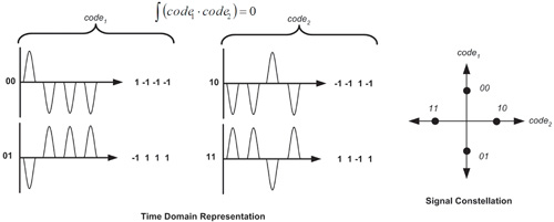 A lowband system in the DS-UWB proposal achieves the data rates mentioned in the selection criteria through the configurations in Table 10.B.12. Data rates up to 1320 Mbps are possible.
10.B.4.2 Simultaneously Operating Piconets/SpreadingThe spreading codes support multiple access for up to six piconets within each band for a total of twelve channels. Devices must support the first four channels in the low band. The chip rate Fchip and center frequency fc of each piconet are harmonically related as fc = 3Fchip. The offset chip rates reduce the correlation between data streams and also help to identify piconets. Table 10.B.13 shows the chip rate, center frequency, and spreading code set for each piconet channel.
Table 10.B.14 lists the different codes for each piconet channel. The piconets use the length-24 codes during acquisition (which always uses BPSK) and for BPSK data transmission with a spreading rate of 24. The length-24 codes are ternary codes, which means that they may take the values {1, 0, 1}. 4-BOK and BPSK with spreading rates less than 12 use identical codes for each piconet during data transmission. 4-BOK uses two codes and their inverses, whereas BPSK uses only one code (code1 in Table 10.B.14) and its inverse. The length-1 and length-3 codes do not support 4-BOK because there is only one code in the set. The code length depends on the desired data rate.
As the number of piconets increases, performance degrades gracefully. Table 10.B.15 shows the required separation distance between piconets in order for each piconet to operate without significant performance degradation. The system is operating in the lower band at 110 Mbps. Multiple access within a piconet is TDMA as in the IEEE 802.15.3 MAC.
10.B.4.3 AcquisitionThe DS-UWB proposal also specifies the frame structure for a data packet, which includes the PLCP preamble, the 2-byte start of frame delimiter (SFD), and the 2-byte PHY header as shown in Figure 10.B.18 [77]. In the PHY header, the seed identifier provides the receiver with the seed for the data scrambler. Next, the data rate is determined by the FEC type, spreading code length, and modulation type. The FEC can have a rate of ½, ¾, or 1 with a K = 6 or a K = 4 convolutional encoder. The modulation type is either BPSK or 4-BOK, and the spreading rate is 24, 12 6, 4, 3, 2, or 1. The interleaver type currently has only one choice of a convolutional bit interleaver. Finally, the last 14 bits specify the length in octets of the frame body, but only 11 bits are used to limit the length to 2,047 octets. The MAC header is 2 bytes and is identical to the IEEE 802.15.3 header. Figure 10.B.18. Frame Structure with PHY Preamble.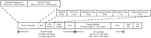 The sequence of bits up to the MAC header is transmitted without FEC or interleaving at a nominal data rate of 55 Mbps in the low band and at 110 Mbps in the high band. The PHY preamble and header are not scrambled, as is the rest of the packet. The spreading rate is 24, so the chips are transmitted at 1,320 Mcps. The payload may be sent at higher bit rates depending on the spreading rate, coding rate, and modulation type. The DS-UWB proposal uses three preamble lengths, which are link quality dependant. Each preamble consists of an acquisition sequence followed by a training sequence, which estimates the channel for rake tuning and channel equalization. The transmitter modulates the length-24 spreading code with random data during the acquisition sequence, and Table 10.B.16 shows the training sequences for the medium preamble length. The short preamble length is a total of 10 ms long and is used for short-range (less than 4 meters) operation with a high data rate. The medium preamble sequence is 15 ms long and is used for medium-range communication (approximately 10 meters). Finally, the long preamble is 30 ms long and is used for long-range communication.[3]
10.B.4.4 ArchitectureAs shown in Figure 10.B.19, a DS-UWB transmitter is similar to a direct sequence spread spectrum (DSSS) system with BPSK or 4-BOK modulation. The process begins with bit randomization through a 15-bit scrambler with g(D) = 1+D14+D15 and the transmitter sequences through four initial values. Then, the FEC encoding is either through the mandatory K = 6 convolutional coder or through the optional, simpler K = 4 convolutional encoder. Both are rate ½ coders that also support a coding rate of ¾ through puncturing. The K = 4 encoder has generator polynomials (158, 178), and the K = 6 encoder has generator polynomials (658, 578). Next, the coded bits are interleaved with a convolutional interleaver to protect against burst errors. Figure 10.B.20 shows the architecture of a convolutional interleaver, which is simpler and incurs less latency than a block interleaver. In Figure 10.B.20, each chip of a coded bit is shifted into a different register from top to bottom. The top register has no delay elements, and each successively lower register provides J = 7 more delays than the one above. After reaching the tenth register, the process repeats again from the top. Following the interleaving process, the bits are mapped to a spreading code that depends on the spreading rate and the modulation scheme. A 30% excess bandwidth, RRC filter shapes the chips to protect against ISI, and the shaped pulses are modulated to an appropriate center frequency that depends on the piconet number. Figure 10.B.19. Transmitter Architecture for the DS-UWB Proposal [76].SOURCE: R. Fisher, R. Kohno, H. Ogawa, H. Zhang, M. McLaughlin, and M. Welborn, "DS-UWB Proposal Update," doc.: IEEE 802.15-04/140r3 [76]. © IEEE, 2004. Used by permission. 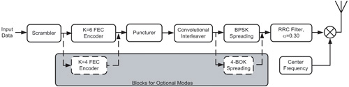 Figure 10.B.20. Convolutional Interleaver [77].SOURCE: R. Fisher, R. Kohno, H. Ogawa, H. Zhang, M. McLaughlin, and M. Welborn, "DS-UWB Physical Layer Submission to 802.15 Task group 3a," doc.: IEEE 802.15-04/137r0 [77]. © IEEE, 2004. Used by permission. Following demodulation, the receiver performs the reverse operations of the transmitter, as shown in Figure 10.B.21. The receiver uses both I and Q channels for the complex RAKE receiver, and it is suggested to use 16 fingers for operation at 110 Mbps and fewer fingers at higher data rates. Figure 10.B.21. Receiver Architecture for the DS-UWB Proposal [76].SOURCE: R. Fisher, R. Kohno, H. Ogawa, H. Zhang, M. McLaughlin, and M. Welborn, "DS-UWB Proposal Update," doc.: IEEE 802.15-04/140r3 [76]. © IEEE, 2004. Used by permission. 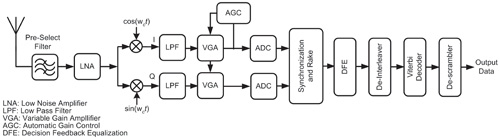 10.B.4.5 PerformanceThe DS-UWB proposal provides flexibility in a number of areas. The optional hardware coding and modulation modes allow a trade-off between reduced complexity and performance. Further, it accommodates flexible spectral allocation with either notched filtering techniques or soft spectrum adaptation, which controls the pulse shape to flatten the spectrum and to insert "notches" that protect sensitive frequencies [78, 79]. The spreading codes achieve up to approximately 14 dB spreading gain and result in a Gaussian amplitude distribution of signals. Further attenuation of narrowband signals can be achieved with a notched filter at the receiver input. Most importantly, the DS-UWB proposal maintains the advantages of a single signal with ultra wide bandwidth. Because each pulse has a wide bandwidth, the DS-UWB proposal is less likely to experience deep fades. Finally, the wide instantaneous bandwidth of each pulse is more suitable for ranging purposes because range accuracy improves with bandwidth. A unique capability of the DS-UWB proposal is its ability to provide the clear channel assessment (CCA) that distinguishes piconets with the offset carrier frequencies. As computed in Table 10.B.3, the link budget specifies a link margin that describes the tolerance of a system to additional sources of loss. The receiver sensitivity level specifies a corresponding minimum signal level that a receiver could detect and successfully demodulate a signal. Table 10.B.17 shows the link margin for the DS-UWB proposal.
The frame structure of the DS-UWB proposal differs from MB-OFDM in the length of time for the preamble. For the DS-UWB proposal, the preamble length depends on channel conditions so it may be slightly more or less than the MB-OFDM preamble length. Table 10.B.18 displays the maximum achievable data rates with frame overhead for a payload length of 1,024 bytes and a medium length preamble. From Table 10.B.18, the data rate increases as the number of frames increases due to the shorter burst mode header. Higher raw data rates suffer more speed degradation from the PHY header because it is sent at the slowest data rate of 55 Mbps, and hence lasts for a larger proportion of time as compared to the data, which is sent at a higher data rate.
The final measure of performance is the distance at which the system achieves each of the raw data rates specified by the selection criteria. Table 10.B.19 tabulates the distance at which the DS-UWB proposal achieves a PER of 8% for the best 90% of the channels. The figures account for a fully impaired simulation with loss from ADC degradation, multipath degradation, and channel estimation.
10.B.5. SummaryThis appendix has introduced the 802.15.3 MAC and the requirements for a UWB PHY for the 802.15.3a standard. It has reviewed two proposals based on these requirements, but either proposal may become an industry standard for WPANs outside of the IEEE standardization process. Both proposals demonstrate good performance as compared to the selection criteria and have strong support from their respective special interest groups. Current trends indicate that future UWB PHYs will be tailored to more applications than WPANs. Further, UWB networking standards will grow to include a MAC that supports mesh networking and better multihop routing for ad hoc networks. The upcoming IEEE 802.15.4a standard promises a PHY for more pervasive networking that also has mandatory location awareness. This appendix was based on the proposals, presentations, and articles on the Web page of the IEEE 802.15.3a Task Group: http://grouper.ieee.org/groups/802/15/pub/. | |||||||||||||||||||||||||||||||||||||||||||||||||||||||||||||||||||||||||||||||||||||||||||||||||||||||||||||||||||||||||||||||||||||||||||||||||||||||||||||||||||||||||||||||||||||||||||||||||||||||||||||||||||||||||||||||||||||||||||||||||||||||||||||||||||||||||||||||||||||||||||||||||||||||||||||||||||||||||||||||||||||||||||||||||||||||||||||||||||||||||||||||||||||||||||||||||||||||||||||||||||||||||||||||||||||||||||||||||||||||||||||||||||||||||||||||||||||||||||||||||||||||||||||||||||||||||||||||||||||||||||||||||||||||||||||||||||||||||||||||||||||||||||||||||||||||||||||||||||||||||||||||||||||||||||||||||||||||||||||||||||||||||||||||||||||||||||||||||||||||||||||||||||||||||||||||||||||||||||||||||||||||||||||||||||
|
EAN: 2147483647
Pages: 110