Section 10.3. Case Studies
|
10.3. Case StudiesEven before the FCC authorized UWB communications, a number of commercial products had already been developed under a special waiver from the FCC. The following products provide an overview of some implementation issues not covered in the standards. Investigation of these commercial products also demonstrates the requirements of UWB systems that are critical for proper operation. For each product, we attempt to describe the system type, modulation scheme, band plan, coding scheme, spreading scheme, MAC layer, networking capability, hardware architecture, and performance. Table 10.2 summarizes the characteristics of these existing products. Table 10.2. Characteristics of Various UWB Chipsets [View Full Width] 10.3.1. XtremeSpectrum Incorporated (XSI)/Motorola Trinity ChipsetXSI demonstrated the Trinity chipset in July 2002 [35]. Trinity is the first commercial, unlicensed UWB chipset targeted to operate under the recent FCC rules regarding UWB. XSI has been active in IEEE 802.15.3a standardization efforts and champions the DS-UWB approach, which shares similar communications methods with the Trinity chipset. A description of DS-UWB can be found in Appendix B. The Trinity chipset is named for three target features of UWB: low price, low power, and high data rate. It is marketed for WPAN applications, such as a wire replacement for streaming MPEG2 video, and for wireless access to fast Ethernet, USB2, and IEEE 1394 ports. The chipset is an I-UWB system with biphase modulation, which is also known as Antipodal Pulse Amplitude Modulation (A-PAM). Both A-PAM and biphase modulation result in the same signal constellation; however, biphase modulation has specifically been patented by XSI for UWB. Biphase modulation is the most energy-efficient binary modulation scheme. The Trinity chipset uses a high Pulse Repetition Frequency (PRF) and long spreading codes to compensate for the energy reduction in average power, and the energy reduction due to ISI. The pulse train fills the spectrum in the range of 3.15.0 GHz. Trinity implements the IEEE 802.15.3 MAC protocol, which is a centralized Time Division Multiple Access (TDMA) protocol (see Appendix B) [36]. The IEEE 802.15.3 MAC supports QoS, which is necessary for video networking; multiple video streams are guaranteed the bandwidth they need for acceptable video quality. The chipset supports up to 8 nodes in a piconet. Full networking support is outside the scope of the IEEE 802.15.3 protocol, which only specifies a MAC protocol and a physical layer. Higher layers may determine the method of routing according to the demands of a particular network application. Because most applications of the Trinity chipset are for WPANs, the chips will likely not require networking support outside of a piconet. The chipset achieves a total power consumption of 200 mW, which is suitable for battery powered components. Depending on channel conditions, the FEC rate can be traded for the data rate. The FEC options are rate ½, rate ¾, and no coding, which support multiple data rates of 50, 75, and 100 Mbps. The maximum range is 10 meters, which is suitable for WPAN applications. Motorola markets revisions of the Trinity chipset under the name XtremeSpectrum chipset. 10.3.2. Time Domain CorpPulsON ChipsetTime Domain Corporation (TDC) markets the PulsON family of UWB chips for a wide range of applications, including indoor wireless networking, video transmission, voice transmission, personnel location, asset tracking, precision measurement, through-walls sensing, industrial sensing, robotic controls, and security systems [15, 39, 40]. TDC was founded in 1987 to commercialize UWB products using the PulsON technology. The first products from TDC were mainly in response to SBIR grants and military and government contracts. Early on, TDC produced prototypes for radar and communications applications for public safety devices under a special license from the FCC. Recently, TDC also has contributed to standardization efforts for both IEEE 802.15.3a and 802.15.4a. TDC premiered the PulsON 100 UWB chipset in 1999 and introduced the next generation PulsON 200 in 2002. These chipsets were originally designed for use in early cellular telephone systems costing under $200a far cry from the sub-$5 WPAN applications. The PulsON 100 chipset was manufactured prior to FCC regulations, but the PulsON 200 chipset meets the FCC regulations for commercial UWB products. The PulsON chipset is an I-UWB system that implements Time Modulated UWB (TM-UWB), which is also known as pulse position modulation (PPM). The transmitter is a single transistor that produces a step waveform that is filtered to produce a monocycle. The receiver uses a matched filtering technique to demodulate the received PPM signal. To overcome the speed limitations of CMOS digital clocks, TDC uses SiGe technology for their PulsON chips. SiGe clocks have picosecond resolutions and low jitter to enable synchronization through fine-grained sliding correlation. Digital timing control achieves coarse resolution, and analog control refines the resolution to a few picoseconds or less. Because correlation is performed in the analog domain, the receiver only has to operate and lock at the pulse rate, which is much less than the time resolution for synchronization. The architecture of the PulsON T100 transmitter and receiver is shown in Figure 10.4. Figure 10.4. Transmitter and Receiver Architecture for PulsON 100 Chipset.SOURCE: D. Kelley, S. Reinhardt, R. Stanley, M. Einhorn, "PulsON second generation timing chip: enabling UWB through precise timing," 2002 IEEE Conference on Ultra Wideband Systems and Technologies Digest of Papers [39]. © IEEE, 2002. Used by permission.  The PulsON 100 chipset is divided into three blocks: a precision timing system, a correlator system, and a digital baseband signal processing and control unit. The T1 timing chip has a resolution of better than 3 ps. The T2 is a second-generation timing chip with a resolution of 1.5 ps. Both chips are a mixed signal design with analog, RF, and digital components. The T1 chip was fabricated using 0.5 µm 45 GHz Si/SiGe heterojunction bipolar transistor (HBT) technology with 0.4 µm PMOS devices and polysilicon resistors. The T2 is implemented in 0.35 µm SiGe. The correlator chip C1 is also implemented in SiGe. The baseband unit operates at the pulse rate and performs signal processing and control functions. TDC also patented one of the first wideband antennas, which has a 1.9 GHz bandwidth and dimensions of 5 cm x 7 cm x 0.7 cm. For multiple access, TDC advocates time hopping with any random pseudo noise codes that produce good autocorrelation and cross-correlation properties. The PulsON 100 provides a moderate data rate of 5 Mbps or a long-range data rate of 16 Kbps at 300 m using directional antennas. The data rate is limited both by the pulse rate and the length of the code used for multiple access. The PulseON 200 provides data rates of up to 9.6 Mbps, but at distances of less than 20 meters. PulsON chipsets also have the ability to ascertain distance to within 1 cm for the purpose of augmenting GPS systems. 10.3.3. Multispectral Solutions Incorporated (MSSI)MSSI's products include a wide range of radar and communications systems for military and civilian use [41], and this section reviews some exemplary systems in these categories. MSSI is active in standardization efforts for both IEEE 802.15.3a and 802.15.4a. Early Communications SystemsDraco, HFUWB, and OrionMSSI's earliest systems were implemented under a special FCC waiver and included long-range communications devices for the military [42, 43]. Three such systems are briefly reviewed here: Draco, HFUWB, and Orion. Draco implements a fully distributed peer-to-peer, ad hoc, multihop network for long-distance communication over a few kilometers. Orthogonal frequency bands provide multiple channels to separate control and data traffic. A separate control channel is dedicated to the periodic transfer of routing and link state information. TDMA provides multiple access within a cell. Draco provides secure communications and obtains a relatively high aggregate data rate by using one bit per pulse (no spreading gain). It protects against channel errors with a Reed-Solomon code. Another communications system, HFUWB, provides long-range communications in non-line-of-sight (NLOS) conditions. I-UWB systems become more susceptible to multipath effects as the transmitter-receiver distance increases relative to the antenna height. This is because the differential path length between multipath components becomes shorter as the distance between them increases. It becomes picoseconds for distances of a kilometer of more, so that even multipath components from short pulses may overlap and can potentially cancel each other out. Therefore, for long-distance communication, the HFUWB system operates in the 30 MHz50 MHz military band to take advantage of low-loss surface propagation and ducting along the earth/atmosphere boundary. By operating in this band, the HFUWB system avoids potential multipath distortion that hampers long-distance communication due to ground reflections [43]. The HFUWB system operates at a data rate of 850 kbps, the average power is 6 W, and the peak power is 120 W. The antenna is quite large due to the low frequency band, but it achieves a range of 60 nautical miles (1 nautical mile = 1.1508 miles = 1.852 km) over water. Finally, the Orion system offers both short-range and long-range communications. Short-range operation is in the 1.31.7 GHz band with a peak power of 0.8 W, a range of 1 km for LOS conditions, and a data rate of 128 kbps for Continuously Variable Slope Detect (CVSD) encoded voice data, and 115.2 kbps for RS-232 data. Orion also uses a modified HFUWB transceiver for long-range operation. Aircraft Wireless Intercommunications System (AWICS)AWICS was created to eliminate cords in aircraft, which can impede mobility and cause dangerous entanglements in crashes [44, 45]. AWICS avoids the multipath induced fading over short distances that is inherent in narrowband communications systems. The AWICS provides reliable transmission in the presence of existing radios on large CH-53E or CH-46E helicopters. Low-power UWB will not interfere with existing aircraft systems and has low probability of detection and intercept, which is necessary to prevent hostile forces from eavesdropping or determining the aircraft position based on electromagnetic radiation. A mobile AWICS transceiver is pictured in Figure 10.5, and Figure 10.6 shows the system architecture of an AWICS transceiver. Figure 10.5. MSSI AWICS System.SOURCE: R. Fontana, E. Richley, and J. Barney, "Ultra wideband technology for aircraft wireless intercommunications systems (AWICS) design," Proc. IEEE Conference on Ultra Wideband Systems and Technologies [44]. © IEEE, 2003. Used by permission. Figure 10.6. System Architecture of AWICS.SOURCE: R. Fontana, E. Richley, and J. Barney, "Ultra wideband technology for aircraft wireless intercommunications systems (AWICS) design," Proc. IEEE Conference on Ultra Wideband Systems and Technologies [44]. © IEEE, 2003. Used by permission. AWICS operates by transmitting 2.5 ns wide pulses at a pulse repetition frequency (PRF) of 2.048 MHz, and because there is no spreading, the raw data rate is also 2.048 Mbps. The 2.048 MHz PRF results in an approximately 500 ns time period between pulses to combat destructive ISI from multipath components. The 500 ns window allows multipaths to "ring down" until they contribute negligible interference to the next symbol. 500 ns translates to a round-trip distance of about 500 feet and ensures that multipath reflections inside the aircraft dissipate before the next pulse. Voice data is sent with a continuously variable slope detection (CVSD) codec for high-quality reproduction. The system uses TDMA with 500 µs long slots, and the superframe format accommodates up to 31 users and the base station. Individual packets have an 8 byte synchronization preamble followed by a 64 byte CVSD packet, a 1 byte ID, and 10 bytes of Reed-Solomon FEC. Synchronization occurs for each packet, and there is a training sequence to provide receiver gain control. The network is a star topology with a central base unit. The AWICS antenna is a dielectrically loaded wideband helix structure. With an outer shell that is waterproof, shock resistant, and G-force tolerant, the transceivers measure 5.25 x 3.5 x 1.5 inches. The mobile units are small enough to be comfortably worn on a vest, and they operate for up to eight hours on battery power. Precision Asset Location (PAL) SystemMSSI has also produced a Precision Asset Location (PAL) system that uses the precise location ability of UWB [4648]. The PAL650 is an FCC-compliant asset location system that locates tags in three dimensions in harsh multipath conditions. The technology was originally developed for DARPA for soldier tracking in urban terrain and for the U.S. Navy for tracking containers in naval cargo holds. The demand grew out of 1991's Operation Desert Storm, which required the shipment of over 40,000 containers; 25,000 of these containers had to be opened and inspected by hand due to inaccurate and lost manifests. The General Accounting Office (GAO) has estimated a three billion dollar loss from the lost and misplaced materials in Operation Desert Storm. Recently, the system has been commercialized for use in warehouses, shipping, supermarkets, retail establishments, robotics, manufacturing, security, and hospitals. In a metal cargo hold, the large space combined with metal walls creates long multipath effects that may last up to 5 µs. Further, stacked containers create severe NLOS conditions. Narrowband systems are ineffective in such environments, but the PAL650 can resolve locations within one foot, even in severe multipath environments. The PAL650 system consists of four passive UWB receivers, a reference tag, a collection of active tags, and a central hub that connects to a computer. Figure 10.7 displays the following system components: a tag, a receiver, and the central processing hub. Figure 10.8 shows a typical arrangement of these components in a deployed system. Figure 10.7. MSSI Precision Asset Location SystemSOURCE: A. Ameti, R. Fontana, E. Knight, and E. Richley, "Commercialization of an ultra wideband precision asset location system," Proc. 2003 IEEE Conference on Ultra Wideband Systems and Technologies [47]. © IEEE, 2003. Used by permission. Figure 10.8. System Layout of PAL650.SOURCE: R. J. Fontana and S. J. Gunderson, "Ultra-wideband precision asset location system," IEEE Conference on Ultra Wideband Systems and Technologies Digest of Papers [46]. © IEEE, 2002. Used by permission. 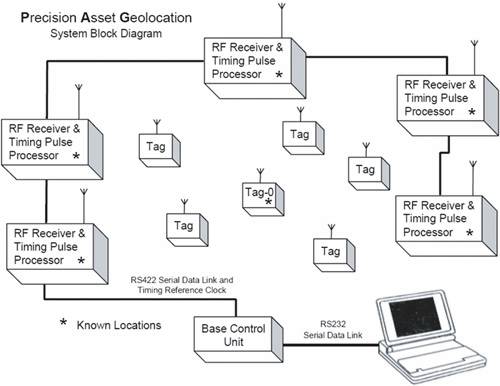 In the PAL650 system, the tags (which contain an I-UWB transmitter but not a receiver) are affixed to containers. The transmitter periodically broadcasts data packets, which are 40 bits in length and consist of a synchronization preamble and tag ID. Packets may be broadcast up to 5,200 times per second without exceeding the FCC limits. Prototype systems use an interupdate time of either 1 second or 5 seconds. With a 5 second interupdate period, the peak power can be as high as 0.25 W and still result in an average power of 5 nW (or 79 dBm/MHz). Thus, the system is able to trade the update rate for a higher peak power and longer range. The PAL650 system has no MAC protocol because the data rate is high, the packets are short, and the transmissions are infrequent. When collisions occur, the data is simply discarded, with the idea that devices will not be inadvertently synchronized and cause repeated collisions. A small, random phase shift programmed into each tag can help eliminate the problem of inadvertently synchronized tags. The receivers contain two separate boards: one for RF circuitry and pulse detection and the other for control and interfacing. Note that four reference points are required to unambiguously locate a tag in three-dimensional space. Each of four receivers records the arrival time of the leading edge of a pulse via a tunnel diode detector. The four receivers are connected with Category-5 Ethernet cable to provide an absolute time reference and synchronization. The arrival times are relayed to the hub and the computer, which uses a nonlinear optimization algorithm to determine the 3-D components. This type of ranging algorithm is known as a time difference of arrival (TDOA) approach. In NLOS conditions, more than four receivers may be used to improve the reliability of the location estimate. However, too many receivers results in an overconstrained set of equations. The likely position for each tag is then determined with a method-of-steepest descent search to minimize an error function. At system initialization, the reference tag is placed at a known location and it calibrates the system. A four-receiver prototype was tested aboard the SS Curtis in Port Hueneme, CA, as a representative environment with severe multipath effects. The system performed with 35 ft RMS errors in open space, 3 ft RMS errors with single stacked containers, and 1112 ft RMS accuracy with double stacked containers. In the commercial system, a single Lithium cell battery provides an operational lifetime of over 3.8 years. The tag measures 1 7/8 inches diameter by 7/8 inches high. The receivers can operate with a minimum SNR of 8 dB. The precision asset location system has a maximum 2 km range outdoors and 300 feet indoors. Micro Air Vehicle Collision Avoidance System (MAVCAS)One unique application of UWB radar is for small, unmanned Micro Air Vehicles (MAVs), which are defined as aircraft less than 6 inches in any dimension, possibly even as small as insects [49]. MAVs may operate cooperatively or alone to provide such applications as battlefield reconnaissance, urban surveillance, communications relays, search and rescue, remote sensing, traffic monitoring, or pollution monitoring. Until recently, MAVs have been impractical due to the strict size, weight, and power constraints of sensor devices. Because these vehicles are unmanned, they require collision avoidance and altimetry sensors to navigate complex topographies. Table 10.3 lists the strict requirements for implementation of MAVCAS and Figure 10.9 shows a prototype MAVCAS system. Figure 10.9. MSSI MAVCAS Prototype.SOURCE: R. J. Fontana, E. A. Richley, A. J. Marzullo, L. C. Beard, and R. W. T. Mulloy, "An ultra wideband radar for micro air vehicle applications," IEEE Conference on Ultra Wideband Systems and Technologies Digest of Papers [49]. © IEEE, 2002. Used by permission.
The MAVCAS transmitter operates by taking a C-Band oscillator, filtering it, and time gating it to produce the result shown in Figure 10.10. At the receiver, the signal is split into two paths, one of which is delayed by 2 nanoseconds. Both signals are then sampled in parallel every 4 ns with a 250 MHz clock so that the receiver achieves a 2 nanosecond time resolution (for positioning accuracy of less than 1 foot). With additional delayed versions of the input signal processed in parallel, the receiver could attain finer and finer precision. The prototype system uses discrete RF components; however, the design can be integrated to meet the size and weight requirements of a MAV. Figure 10.10. Bandpass Pulse Shape for MAVCAS in the Time Domain.SOURCE: R. J. Fontana, E. A. Richley, A. J. Marzullo, L. C. Beard, and R. W. T. Mulloy, "An ultra wideband radar for micro air vehicle applications," IEEE Conference on Ultra Wideband Systems and Technologies Digest of Papers [49]. © IEEE, 2002. Used by permission. 10.3.4. Aether Wire and Location LocalizersAether Wire and Location, Inc. is developing pager-sized units that are capable of localization to centimeter accuracy over distances of kilometers in networks of hundreds or thousands of nodes [5053]. The units, currently named Localizers, use UWB to provide low-cost, long-distance communication along with precise ranging capability. The design objective is to fabricate complete transceivers integrated on CMOS technology. The first-generation Localizer was fabricated in July 1994, and four generations have been fabricated since that time. The localizers define their position relative to other localizers, instead of a fixed point as in GPS. The devices are meant to operate in urban canyons, forests, and indoors for a variety of applications, including sensor networks, soldier visualization, surveying and construction, tracking, inventory control, rescue, camera focusing, smart highways, machine control, and smart homes. Military applications include distinguishing friend from foe, logistics control, ground surveillance through sensor networks, and mine detection and clearing. Figure 10.11 displays the size of the system relative to a dime, and the layout of the transmitter and the receiver. Figure 10.11. Localizer System.SOURCE: R. Fleming and C. Kushner, "Integrated ultra-wideband localizers," 1999 Ultra-Wideband Conference [51]. © Aether Wire & Location, Inc., 1999. Used by permission. The localizers are I-UWB systems, but their pulse shape is unique due to the characteristics of the transmit antenna. Each "pulse" is, in fact, a series of two pulses: one with positive polarity and one with negative polarity. The pulses are sent in opposite pairs because the antenna is a Large-Current Radiator Antenna. The transmitter applies current steps to the antenna to generate pulses. Turning the current on generates a positive impulse, and turning the current off generates a negative impulse. The pairing of antipodal pulses prevents a run of identical symbols from building an impractically large current. Because the system is a DS-UWB system, each pulse pair forms a chip. Each pulse is 1 ns wide with a 5 ns spacing between pairs. A logic 1 consists of a positive pulse followed by a negative pulse, and a logic 0 consists of a negative pulse followed by a positive pulse. One advantage of this unique pulse shape is that thoughtful spacing between pulse pairs places nulls in strategic locations, that is, frequencies where narrowband interference may exist [54]. For 1 ns pulse width and 5 ns spacing, the energy lies between 100 MHz and 1 GHz with nulls every 200 MHz (1/spacing). The receiver is based on a time integrating correlator (TIC), which is pictured in Figure 10.12. A TIC is the dual of a normal correlator that multiplies and then integrates. For a TIC, the received signal is stored and a reference code is moved past the analog input signal. Then, the product of the received signal and the code are summed in a bank of parallel analog integrators. Each parallel correlator uses an identical copy of the code, but shifted by a slightly different time delay. When the received signal is aligned with the proper code sequence, the integrator produces an increasing output that eventually reaches a maximum. Figure 10.12. Pulse Pair, Offset Spreading Sequences, and TIC Output.SOURCE: R. Fleming and C. Kushner, "Low-Power, Miniature, Distributed Position Location and Communication Devices Using Ultra-Wideband, Nonsinusoidal Communication Technology," Semi-Annual Technical ReportARPA [50]. © Aether Wire & Location, Inc., 1995. Used by permission.  The localizers must be synchronized for accurate ranging because the ranging is based on the time of flight. During synchronization, a node searches for a particular code as well as its specific start time. Because the search process may take some time, the initiating node repeats its sequence for a sufficiently long period to ensure detection by the target node. Localizers achieve fast synchronization by using Kasami sequences, which have the special property that the side lobes of the autocorrelation are detectable with only partial overlap of the transmission and the code [55]. Therefore, if no signal is detected, the time step can advance immediately. After the target node synchronizes to the initiating node, the target then sends a synchronization code to the initiator, which ensures that both nodes are synchronized to the same reference clock and the time of flight can be accurately measured. The distance between localizers is measured by multiplying the round-trip time by the speed of light. Note that the return signal is not an echo, but a completely new transmission, so the known circuit delays must be factored into the time of flight measurement. Then, the relative location of each localizer is determined cooperatively. Each pair notes the distance between them, and five or more localizers share this information to determine the three-dimensional positions relative to one another. The localizers group themselves into clusters and form bridges between the clusters. Within clusters, multiple access is TDMA. Among clusters, multiple access is CDMA, where each cluster uses a different spreading code to mitigate cross-cluster interference. Multihop routing through clusters provides long-distance communication. The fourth-generation receiver/controller chip has 32 parallel TICs, a 60 dB variable gain LNA, a real-time clock, a code generator, and a transmit antenna driver. The chip is fabricated in 0.35 µm CMOS, with single ended and differential current steering logic, and differential series pass logic families. The internally generated RF noise is reduced by placing most hardware on-chip to avoid high power connections, by using low noise logic for receiver functions, by disabling CMOS components during reception, and by using differential circuits while transmitting. The overall die size is 10 mm2, including the processor, RAM, and ROM. The cost is about 50 cents, and the idling power is 30 µW. The fourth-generation chips have a positioning accuracy within 1 cm and a range of 30-60 m. 10.3.5. 802.15.3aAt the time of this writing, the IEEE 802.15.3a standard for WPAN applications is still under consideration. It will use a MAC similar to the IEEE 802.15.3 MAC, and the physical layer will be selected from two proposals: multiband orthogonal frequency division multiplexing (MB-OFDM) or direct sequence UWB (DS-UWB). The 802.15.3 MAC and the above physical layer proposals are described in detail in Appendix B. 10.3.6. 802.15.4a DevicesAt the time of this writing, the IEEE 802.15.4a standard [24, 56] is in the early stages of development, and it should extend the capabilities of IEEE 802.15.4 with a UWB physical layer that offers ranging capability, more robust operation in harsh environments, and increased link distances. The call for proposals was released in July 2004, and should spawn innovative ideas for addressing a number of the design issues listed in Table 10.2. This section provides an overview of some possible issues that the standard may address. IEEE 802.15.4 devices require low-power dissipation, and the additional UWB physical layer should further decrease the power consumption. For the existing physical layer, the minimum transmit power is 1 mW, whereas for UWB, the maximum transmit power allowed is 0.5 mW. The type of application will determine many architectural considerations in the lower layers. Different applications have different traffic profiles. For low data rate applications, the traffic profiles include periodic data, such as temperature sensors; intermittent data such as perimeter sensors; or repetitive, low latency data, such as the movement of a computer mouse. At the network level, an increased range and dense topology means that the networking layer should accommodate more nodes than the 802.15.3 WPAN, and also offer multihop routing. The existing IEEE 802.15.4 standard offers several topologies to improve multihop performance. The two topologies currently supported in IEEE 802.15.4 are star and peer-to-peer topologies, and they can be combined in a hybrid topology as shown in Figure 10.13. Figure 10.13. Example IEEE 802.15.4 Topology.SOURCE: P. Gorday, J. Martinez, and P. Jamieson, "IEEE 802.15.4 overview," IEEE P802.15 Working Group for Wireless Personal Area Networks Publications [56]). © IEEE, 2001. Used by permission. In a star topology, all nodes send data through a smart, central coordinator, such as a PC or PDA. The terminal devices may be unsophisticated and designed to operate for long periods of time on battery power. In a peer-to-peer topology, nodes can communicate with any neighbor, and the resulting mesh topology is suitable for such applications as sensor networks. Large dense networks, such as sensor networks, will require a multihop routing protocol. The hybrid topology pictured in Figure 10.13 offers the most flexibility. Local groups of nodes may be connected in either a star topology or a mesh topology, and the local groups are connected via a cluster tree topology. In this topology, there is the possibility of some nodes being full function devices (FFD) and others being reduced function devices (RFD). An FFD can coordinate an entire WPAN or a cluster, whereas an RFD is a simple device that communicates only through FFDs. An FFD could be a DVD, TV, computer, or PDA, whereas an RFD could be a light switch or a passive infrared sensor. In the existing 802.15.4 standard, multiple access is mainly through Carrier Sense Multiple Access with Collision Avoidance (CSMA/CA). Because many devices do not have QoS constraints, they can operate without a beacon or central coordinator to reduce overhead. Power reduction is obtained through a very low duty cycle operation (for example, the device may be in an "awake" state for less than 0.1% of the time), so some devices may require MAC level synchronization. In this case, a contention access period (CAP) follows a beacon. Finally, devices with QoS constraints can take advantage of both the optional beacon and the optional guaranteed time slots (GTS). The frame structure is shown in Figure 10.14 [56]. Figure 10.14. Frame Structure of IEEE 802.15.4 MAC. The dependence on CSMA/CA presents a problem for UWB systems, namely, the method of clear channel assessment (CCA). In I-UWB, CCA is difficult because a receiver must find a narrow pulse in a relatively long time window. Existing CCA methods for pulses, such as peak detection, matched filtering, sliding correlation, and Interleaved Periodic Correlation Processing (IPCP) [57] may take a prohibitively long time or require expensive hardware. The 802.15.4 MAC requires the following methods of CCA [58]:
Pulse sense has been suggested to provide CCA in I-UWB [63]. Squaring circuits may be used for carrier-based UWB with BPSK signaling. |

|
EAN: 2147483647
Pages: 110