Section 5.5. Spectral Encoded UWB Communication System
|
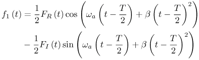
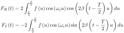
5.5. Spectral Encoded UWB Communication SystemIn this section, we describe a UWB communications system that uses spectral encoding as a multiple access scheme with interference suppression capability [41]. The main advantage of this technique is that transmitted signal spectrum can be conveniently shaped to suppress narrowband interference. The concept of spectral encoding is not new. It has been proposed both for an optical communication system [42, 43] and for wireless communications scenarios [44, 45]. In this technique, a message signal is multiplied by a spreading sequence in the frequency domain, as opposed to conventional direct sequence code division multiaccess systems in which the encoding is in the time domain. As a result, the signal will be spread in time. Multiaccess capability is achieved by assigning distinct spreading sequences to different users. When narrowband interference suppression is desired, a spreading sequence is used that has a spectral null where the narrowband interference is located. Moreover, the narrowband interference is "notched out" at the receiver when the received signal spectrum is multiplied by the conjugate of the transmitted signal spectrum (correlation receiver). Details can be found in [46]. The Fourier Transform of the data signal is performed via a well-established implementation that corresponds to the multiplication and convolution of the desired signal by chirp (linear FM) waveforms. This method of spectrally encoding the UWB signal can suppress narrowband interference and can create spectral nulls where desired, simplifying the requirement to meet the FCC mask. A schematic of the transmitter is shown in Figure 5.30. The modulated signal, f (t), is non-zero only in Equation 5.31 where wa and b are respectively the center frequency and the half slope of the chirp signals, and FR (t) and FI (t) are respectively the real and imaginary components of the Fourier Transform of the modulated signal, f (t), and are given by Equation 5.32 where wc is the carrier frequency. f1 (t) is valid only in t Equation 5.33 Equation 5.34 Figure 5.30. Transmitter Schematic of Spectrally Encoded UWB.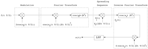 The output transmitted signal s (t) is the inverse Fourier Transform of the signal f2 (t) and is equal to Equation 5.35 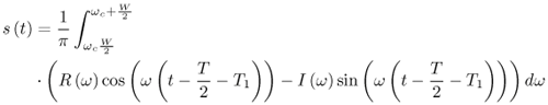 where R (w) and I (w) are defined as R (w) = F (w)PNR (w) and I (w) = F (w)w. PNI (w). W is the bandwidth of f (t). The transmitted signal is valid only in t |
 [
[
|
EAN: 2147483647
Pages: 110