SNMPv3 Message Formats
| RFC 2572 contains the SNMPv3 message format specification; an extract is illustrated in Figure 2-1. The message format is broken down into four overall sections made up of the following:
Both the context and PDU areas are either encrypted or in plain text. The format used for SNMPv3 messages follows a left-to-right and top-to-bottom pattern. So, from Figure 2-1, the first field in the message is MessageVersion , the next field is MessageID , and so on. We describe the SNMPv3 message fields in the following sections. MessageVersionThe first field in the message is the SNMP version. This is located in the same position for all versions of SNMP to allow differentiation during message processing. This provides for backwards and forwards compatibility. A value of 3 in this field indicates an SNMPv3 message. A value of 2 indicates SNMPv2c and a value of 1 indicates SNMPv1. MessageIDThe MessageID is a number used between two entities for message correlation. So, if a manager sends a GetRequest with MessageID x , then it is important that the manager does not re-use x until the outstanding message is answered or timed out. The PDU contains a request ID field, which was used for the same purpose in SNMPv1 and SNMPv2c, but since SNMPv3 allows for encrypted PDUs, the MessageID is in the (unencrypted) header. The MessageID also provides a means by which multiple copies of a response (e.g., if the underlying datagram service duplicates a message) can be distinguished. Messages re-transmitted by a manager should use a new MessageID . MaxMessageSizeThe MaxMessageSize is the maximum message size supported by the sender of the message. This is the largest size packet that the transport protocol can carry without having to use fragmentation. The receiver uses the value of MaxMessageSize to ensure that its reply is within the allowed size range. MessageFlagsThe MessageFlags object is 1-byte long and determines the authentication and privacy settings for the message. It also indicates if this message requires a (report) response from the receiver. The three right-most bit positions are used when encoding this object, and the following are the allowed combinations:
All three of the above may have the report option set. This indicates that a response is required. MessageSecurityThe MessageSecurity is an integer object that indicates the security setting associated with the message. The range of values supported is as follows:
Values above 255 can be used to specify enterprise-specific security models. The receiver must use the same security model when executing its security processing. The security subsystem handles the processing of this section of the SNMPv3 message. Security Model Data: GeneralThe general section of the security model data contains the following fields:
The above fields precede the authentication and privacy data areas. EngineID and UserName are used to form an index into a table called usmUserTable. This table stores the security model data for a given engine ID and user pair. Security Model Data: Authentication ProtocolTwo authentication protocols are supported in SNMPv3, namely MD5 and SHA. Both protocols serve the same purpose: that of authenticating the SNMPv3 message. The MD5 algorithm calculates a 16-byte (128-bit) digest and the first 12 bytes (96 bits) are included as part of the message in the Authentication field in Figure 2-1. The user must select a 16-octet secret key for use in the MD5 algorithm. If the user opts for the SHA authentication algorithm, then the (SHA) algorithm calculates a 20-byte (160-bit) digest and again the first 12 bytes (96 bits) are included as part of the message in the Authentication field in Figure 2-1. The user must select a 20-octet secret key for use in the SHA algorithm. Whichever algorithm is used, the authentication protocol field is a 12-byte octet string used as an electronic fingerprint (or message authentication code) to authenticate the message. It is similar to the cyclic redundancy check (CRC) codes used in many applications (ATM, disk drives , etc.) to verify that data has not been modified in transit. When an SNMP entity (i.e., a manager) wants to send an SNMP request to another entity (i.e., an agent), it must use a secret authentication key (described in the previous paragraph) known to both parties. This key is used to generate the fingerprint. When the authenticated message is received, the fingerprint is recalculated, and if the two match, then the message is deemed to be authentic . Security Model Data: Privacy ProtocolThe privacy protocol field is an 8-byte octet string used for the Data Encryption Standard (DES) algorithm. The encryption uses a 16-byte key. The first 8 octets of the 16-octet secret key are used as a DES key. The second 8 octets are used as an initialization vector; this is a unique 8-octet value that is manipulated to ensure the same value is not used for encrypting different packets. Again, both parties use a secret private key to encrypt and decrypt messages. ContextThe historical background for SNMPv3 context is interesting. It arose from discussions about how to deal with cases in which a given MIB table already exists with a specific indexing scheme, but the indexing scheme must be extended. Some tables in the Bridge MIB are indexed by port number, and in a rack-based system or a stacked system, there may be multiple cards or units with the same port numbering. Contexts were invented to allow multiple instances of the same MIB table within the same SNMP agent in order to handle cases like this. ContextName is an octet string, and ContextID uniquely identifies an entity that may recognize an instance of a context with a particular context name. The context details are considered part of the PDU field. PDUThis object represents either an unencrypted (plaintext) PDU or an encrypted PDU. The value of the MessageFlags object dictates which one is the case. SNMPv3 Security and View-Based Access ControlAn important point to note about the SNMPv3 USM is that it provides authentication and privacy at the message level. The view-based access control mechanism operates at the PDU level and determines if access to a given MIB object should be granted to a principal (or user). These issues are comprehensively covered in [Zeltserman1999]. SNMPv3 Message ExchangesWe now look at some SNMPv3 message exchanges, using Figure 2-2. In an effort to solidify the above concepts, Figure 2-2 has a good deal of detail ”hopefully not too much. Figure 2-2. SNMP GetRequest and GetResponse messages. Figure 2-2 illustrates a network with a management system (containing SNMP Manager A) connected to an IP router. The router has three network interfaces: A, B, and C. It hosts an SNMP agent (Agent A). The management system host is connected to Interface B on the IP router. Router interface A is connected to another network segment on which a server is located. The server hosts SNMP Agent C. Router Interface C is connected to a PC that hosts SNMP Agent B. An important point to note is that the PDU fields in Figure 2-2 are SNMPv2c PDUs; that is, SNMPv3 introduced no new PDUs. So, let's take a look at Figure 2-2 starting with a GetRequest-GetResponse message exchange. SNMPv3 GetRequestManager A in Figure 2-2 wants to retrieve the value of the ipInReceives.0 object instance from Agent B. So, Manager A builds a GetRequest message. The network operator is a little worried about hackers, so the message is authenticated and encrypted before being sent across the network. Step 1 is now complete. Agent B receives the message, processes it (applying the required security processing), and retrieves the required MIB object instance. Next, Agent B builds a response message, applies the required security, and sends the message back to Manager A. Step 2 is now complete. After verifying the message security, Manager A will now extract the required data and store it in some application-specific fashion (usually in a database). A few points can be made about Figure 2-2:
Manager A now has the required data. Usually, an NMS makes many such requests simultaneously , often requesting entire tables at a time. SNMPv3 Get-NextRequestIf Manager A wants to perform a getNextRequest on the ipInReceives.0 object, then the only differences required in Figure 2-2 are as follows:
After this message exchange, Manager A has the required data. SNMPv3 GetBulkRequestGetBulkRequest is a clever way of retrieving a range of objects from a table. The required objects are provided in a variable-bindings list. The objects are retrieved based on the values of two numbers :
So, let's say we want to retrieve the number of interfaces on a given NE and then use that number to retrieve the speed of those interfaces. This can be done with one or more getRequests , but we can do it in one step using getBulkRequest . Our non-repeater is the object interfaces.ifNumber . This value will also be used to specify the max-repetitions for the object interfaces.ifTable.ifEntry.ifSpeed . So, the call to a conceptual GetBulkRequest API might look like the following: GetBulkRequest (non-repeaters = 1, max-repetitions = interfaces.ifNumber, varBindList = {interfaces.ifNumber, interfaces.ifTable.ifEntry.ifSpeed } ) GetBulkRequestNonRepeater = interfaces.ifNumber.0 Type and Value = Integer32 5 =====> So, the number of interfaces is 5 GetBulkRequestMaxRepetitions of 5 =====> We now get the 5 interface speeds Variable = interfaces.ifTable.ifEntry.ifSpeed.1 Value = Gauge32 155000000 Variable = interfaces.ifTable.ifEntry.ifSpeed.2 Value = Gauge32 155000000 Variable = interfaces.ifTable.ifEntry.ifSpeed.3 Value = Gauge32 100000000 Variable = interfaces.ifTable.ifEntry.ifSpeed.4 Value = Gauge32 4294967295 Variable = interfaces.ifTable.ifEntry.ifSpeed.5 Value = Gauge32 4294967295 From this, we can see that the host (in this case, an MPLS label edge router) to which the GetBulkRequest was sent has five high-speed interfaces supporting bit rates of 155Mbps (155000000), 100Mbps (100000000), and 4Gbps (4294967295) respectively. If Manager A wants to execute a getBulkRequest on the IP table, then the only differences required in Figure 2-2 are the following:
After this message exchange, Manager A has the required data. Typically, this type of operation might occur during a discovery procedure; that is, NE x has been found, so we discover its attributes (number and type of interfaces, speeds, etc.). SNMPv3 SetRequestA SetRequest message follows a very similar set of steps. The only differences required in Figure 2-2 are the following:
After this message exchange, Manager A has modified the required data. Typically, this type of operation might occur during a provisioning procedure; that is, we wish to alter some data in NE x, so we execute a set (e.g., add a new row to a MIB table or reset a counter to zero). We will see examples of this in the MPLS MIB tables in Chapters 8 and 9. SNMPv3 NotificationsWe now describe the notification mechanism. A notification message can be either a trap or an inform . Let's now look at an example of a notification. Agent A on the IP router in Figure 2-2 now detects that one of its three network interfaces has gone into the down state (link failure is a commonly occurring hardware fault). This is illustrated in Figure 2-2 with an X on Interface A. It can no longer send or receive network traffic on that interface. The IP router agent has to notify its registered manager of this event, so it sends a notification message to Manager A. Manager A receives the notification, processes it, and realizes that the host for Agent A now has only two working network interfaces. Unfortunately, Manager A can no longer contact SNMP Agent C. Typically, this event would be propagated upwards to a GUI topology, where the associated network link icon (for the link attached to Interface A) would change color to red. Or, the subnet containing the router could change color . Manager A could then poll the router MIB to verify the interface state. The notification has fulfilled its purpose, because the problem can now be resolved. This is the power of notifications: Intelligence is distributed in the SNMP agents , and they emit notifications if and when problems occur. It is then up to the management system to try to resolve the problem if one exists. Notifications do present scalability concerns, particularly as network sizes increase. Many notifications occurring simultaneously can have unforeseen consequences for both the network and the management system. We now briefly describe the notification PDU and start with a look at an SNMPv1 Trap PDU, illustrated in Figure 2-3. Figure 2-3. SNMPv1 trap. The trap PDU fields in Figure 2-3 have the following meanings:
Chapter 7 has an example of some SNMPv1 traps that occur during a security violation (Figure 7-11). We now briefly look at an SNMPv2 trap PDU in Figure 2-4. Figure 2-4. SNMPv2 trap. The fields in Figure 2-4 are identical to those of a get , get-next , or set PDU . The only difference is the type value of 0xA7 . The main difference between this message and an SNMPv1 trap is that the variable-bindings field (often called the varbind ) is made up of:
Each SNMPv2 trap is defined in the MIB using the NOTIFICATION-TYPE macro [Zeltserman1999]. Typically, an NE emits a notification when it wants to inform the manager of some important event or fault, such as a link going into the down state. The last PDU we will look at is the SNMPv2 inform. The only difference between an inform and an SNMPv2 trap is that the type value for an inform is 0xA6 . Informs use a timeout/ retry mechanism in an effort to ensure delivery to the manager. By their nature, notifications occur at undefined moments in time. Once a notification message is received, the NMS must decode it and then try to figure out the origin of the problem. This is sometimes called root-cause analysis, which when successful, allows the network operator to understand the exact nature of the problem that caused the notification. Root-cause analysis should also help the user in fixing the problem (if one exists). Access RightsAn important point to note is that for get and set operations to succeed, the manager must have the appropriate access rights. This means that the access policy (mentioned earlier) must be configured to allow the manager appropriate read and write access. If a manager attempts an operation for which it does not have access privileges, then the operation will fail. Message SizeAnother important point is that SNMP management messages can refer to many objects, not just to one, as in the preceding examples. In other words, the SNMP GetRequest message in Figure 2-2 can include more objects than just the ipInReceives object (up to the maximum size allowed by the transport service). However, agents will generally have a maximum packet size that they can handle. A manager must be prepared to handle the case in which an agent packet-size limit is too small for it to return instances of all objects which the manager requested . In this case, the manager will probably need to separate the requests into multiple packets. SNMPv3 SecurityAs we saw in Figure 2-2, SNMPv3 provides both authentication and encryption (privacy). Authentication is provided by the industry-standard MD5 hashing scheme or by Secure Hash Algorithm (SHA), and privacy is provided by DES. The configuration settings required on the agent side are generally as follows:
The settings for Figure 2-2 consist of authPriv (i.e., both authentication and privacy). The two passwords are used during message encryption and authentication. For enhanced security, it is important that network operators change these passwords regularly. Problems with SNMPSNMP is a far-from-perfect technology. Some of the more serious problems with it include the following:
Despite these shortcomings, the widespread deployment and simplicity of SNMP are among its greatest strengths. The Different Versions of SNMPThe versions of SNMP in widespread commercial use are:
SNMPv1 has community name-based security and includes fairly coarse-grained error handling. For example, when a GetRequest PDU includes more than one variable, then either all or none of the values are returned. A failed SNMP set operation will generally result in the manager receiving a GetResponse PDU containing "Bad Value" and indicating the problem variable. This is of limited use for debugging in operational environments. The issue of "holes" in SNMPv1 tables is particularly troublesome . If a GetRequest is sent to an agent for a given MIB object instance and the object has no value, then the agent replies with a "No such name" error. This is not very useful information and makes tabular retrieval a very fragile proposition. SNMPv2c provides the same security as SNMPv1. It also adds a new message called getBulkRequest (that we saw earlier) that allows multiple rows of tabular data to be retrieved in one operation. It allows the sender to specify that getNext be used for a range of managed objects. SNMPv2c also provides better error reporting than SNMPv1. SNMPv3 also supports the getBulkRequest message and supports three security settings (again, as we saw earlier):
As we have seen, the strong security of SNMPv3 is a compelling reason for its adoption. The configuration of SNMPv1 and SNMPv2c agents consists of community strings (and trap/notification destinations). Usually, two community strings are used, one for gets and one for sets. The "get" password is usually "public" and the "set" password is usually "private." We will see this in action in Chapter 7. SNMPv3 configuration consists of (at a minimum) selecting authentication/encryption protocols and specifying (if applicable ) authentication and encryption passwords. These settings are written to the agents (or SNMPv3 entities) and must then be used by the NMS in its message exchanges with the agents. SNMP Applications: MIB BrowsersMIB browsers are specialized tools used to examine the values of MIB object instances on a given agent. A MIB browser can be a fully integrated GUI-based application or a simple text-based one. Regardless of the packaging, they are indispensable for NMS developers and are also very useful for learning about SNMP. Typically, a MIB browser allows a user to "load up" (or compile) a set of MIB files and then view the values of the associated object instances. If a given object instance value is changed (i.e., set) by an NMS, then the MIB browser allows the user to see (i.e., get) the modified value ”a simple but very powerful facility. Table 2-1 lists the IP Group leaf objects, one of which was seen earlier in Figure 2-2. These object instances are part of the output of a MIB walk on the IP Group from an NT workstation. The tool used to generate this data was the Microsoft Visual C++ SNMPv1 sample program, which is described in Chapter 7. Table 2-1. Sample MIB Walk on the IP Group of a Host
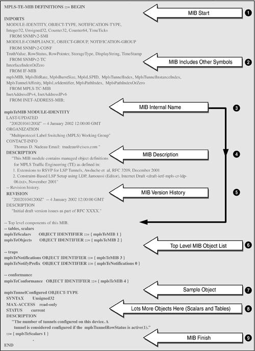
In the MIB object name column, each object has a zero appended. This illustrates the difference between a MIB object definition and its instantiation in a real NE. An instantiated object has a value appended to it. Scalar (nontabular) objects always have zero appended. Tabular objects have an index appended. In the case of the IP Group illustrated in Table 2-1, the objects are all scalar and so have .0 appended. A Closer Look at a MIBLike all great ideas, MIBs are fairly simple to understand. They provide a detailed description of the managed objects supported by a given device. As mentioned earlier, the MIB defines managed objects in a conceptual way, including the syntax and semantic information about each object. These managed objects can then be instantiated as real objects in an agent host device. Figure 2-5 is an extract from one of the draft MPLS MIBs [IETF-TE-MPLS] taken from the IETF Web site. As usual, we try to present the overall picture of a complete MIB. We will examine this MIB more closely in Chapter 8, "Case Study: MPLS Network Management." It illustrates most of the general detail needed to understand MIBs. From Figure 2-5, we can see that MIBs are made up of just a few sections clearly identified by keywords. The main points of Figure 2-5 (identified by numbers and corresponding arrowheads) are the following:
Figure 2-5. An extract from one of the draft-standard MPLS MIBs. Figure 2-5 therefore includes most the elements of a MIB structure that will be encountered in practice. MIB objects can be scalar (such as integers) or tabular (rows of other objects). In Chapter 8 we look closely at tables, particularly the MPLS MIB tables. The objects defined in the MIB are instantiated in the agent host and can be retrieved using a get operation via a MIB browser. Similarly (if they are read-write), they can be modified using a set operation. The SNMP agent asynchronously dispatches device notifications. Notifications are sent to a preconfigured IP address, usually that of the NMS. Managed ObjectsManaged objects are the basic unit of exchange between an NMS and NEs. The managed objects are defined in the MIB and deployed in the network. The NMS provides software that, combined with the managed objects, gives the user the means of operating and maintaining the network. The importance of MIBs and managed objects cannot be overstated. The managed objects defined in the MIB must match the user's needs: not too detailed and also not too coarse-grained. There Is only One MIBOne merit of a standard MIB is ease of extension. As new technologies are invented and deployed, the associated managed objects must be defined in new MIB modules. The latter can then be added to the standard MIB in an orderly fashion, e.g., by using enterprise-specific numbers. New objects can be defined and included in MIB module files, such as the MPLS MIB files we will see in Chapter 8. The objects in such files are implemented in the NEs that support the associated technology (e.g., MPLS). The important point to note is that these are extensions to the standard MIB, i.e., there is only one MIB. Analogy for an NMSIt may be helpful to draw some comparisons between a standard operating system (such as UNIX or Windows 2000) and an NMS. Both provide a set of abstractions to assist in the end use and management of the system. In the case of operating systems, some of the abstract objects are:
These abstract entities map onto real objects that users and applications employ for getting work done. NMS also employ the above objects in addition to other objects specific to network management. These NMS abstract objects are:
These objects are used for managing networks. The NMS employs these objects and provides additional abstractions (GUI, software wizards, etc.) to assist the network operator. |
EAN: 2147483647
Pages: 150