MIBs Again
| In Chapter 8, "Case Study: MPLS Network Management," we studied in some depth the structure and use of two of the IETF MPLS MIBs. These MIBs have been well-designed; for example, a signaled traffic-engineered tunnel created using the mplsTunnelTable can be managed with reference just to the originating node MIB. In other words, it is not necessary to browse every node in the path of the tunnel, because the necessary details are stored in the originating node. This helps improve the manageability and scalability of the MPLS network. In effect, the NMS can manage such tunnels via the LERs in an MPLS network. This has other benefits: LERs are often more powerful devices than the LSRs in the core of the network, so they are potentially more able to withstand large bursts of management plane traffic, for instance, when the tunnels are being discovered . Another important point is that the path taken by the tunnels through the network is also stored in the LER in the (optional) mplsTunnelARHopTable . If this table is supported, then the originating node knows the path. This again avoids the need for delving into the transit LSR MIBs. All of the MIBs we've studied so far have been essentially passive in nature; that is, they serve to record details of the managed network. There is another use that can be made of a MIB: policy storage. In this, the MIB is used to store rules and actions. Policies consist of conditions (or rules) and actions that should be taken when the conditions are met. Later in this chapter, we study the FTN MIB because it provides a framework for storing policies that can be used to manage IP traffic as it enters an MPLS network. Tightly Coupled Intercolumn DependenciesAn important area of MIB design is that of intercolumn dependency in which the value of column X provides a context for column Y, or vice versa. An example is where a tunnel instance is a backup for a primary tunnel as illustrated in Figure 9-1. Figure 9-1. A primary tunnel with a backup instance. In Figure 9-1, we see an MPLS network with two tunnels. One is a primary and the other is a backup. This can be brought about by creating two entries in the mplsTunnelTable , one of which is an instance of the other. By instance, we mean a copy in all things except the path taken. The two tunnels can be configured to share the same set of resources, such as bandwidth, or they can each duplicate the resources. The primary tunnel follows the path {LER1, LSR1, LSR2, LER2}, while the backup follows the path: {LER1, LSR3, LSR4, LER2}. In Figure 9-1, we also see an excerpt from the mplsTunnelTable in LER1. The primary tunnel has the value 1 in both mplsTunnelIndex and mplsTunnelInstance . In other words, it is the first entry in the mplsTunnelTable and is not an instance of another tunnel (i.e., it is an instance of itself). The backup tunnel, however, has the value 1 in mplsTunnelIndex and 2 in mplsTunnelInstance . This means that it occupies the second entry in the mplsTunnelTable and is an instance of mplsTunnelIndex 1. In other words, it is a backup instance of the primary tunnel. Let's consider the steps that must be taken to bring this about using SNMP. To create the primary tunnel, we set the values of mplsTunnelIndex and mplsTunnelInstance both to 1 (as well as setting other mandatory columns , as was seen in Chapter 8). It is likely that we will have looked up the value of the mplsTunnelIndexNext object to get the next free mplsTunnelTable index. To create the backup tunnel, we must consult the MIB (or an external database) for the value of mplsTunnelIndex that corresponds to the primary tunnel ”in this case, 1. We then create another entry in mplsTunnelTable with the mplsTunnelIndex and mplsTunnelInstance values 1 and 2, respectively. So, the value of mplsTunnelInstance serves to indicate if the tunnel is an instance of another tunnel. If two (or more) rows in the tunnel table have the same value of mplsTunnelIndex and different values of mplsTunnelInstance , then they are instances of each other. The tunnel instances can act as backups to each other, or they can load-share incoming traffic. This is an example of intercolumn dependencies in which the value of one column depends on the value of another. In the case of backup (or load-sharing) tunnels, the value of mplsTunnelIndex has the same value as mplsTunnelIndex from another row in the mplsTunnelTable . The two entries are differentiated by the value of mplsTunnelInstance . Such dependencies contribute some complexity to the MIB. For example, should we be allowed to delete a primary tunnel before deleting the backup? Usually not, because the backup generally exists only to protect the primary tunnel. So, the agent on LER1 should enforce this, and the NMS should follow suit. As with many engineering decisions, the best way to implement this is with clear rules, such as precluding deletion of a primary tunnel until all instances have been deleted. The agent should enforce these rules along with the NMS (e.g., if the user attempts to delete a primary tunnel before deleting the backup). It is a bad practice for the NMS to rely on the agent to enforce such rules ”the agent may erroneously permit inconsistencies. For this reason, it is better for the NMS to infer relationships like tunnel instances and enforce rules concerning the order of deletion without relying on the agent. Another important issue is that of providing default values for MIB objects. This can have an important impact on the complexity of the SNMP-handling software in an NMS, as we'll see in the next section. Default Values and Thin Software LayersIf two MIB columns depend semantically on each other, then it is good practice to have default values via the DEFVAL clause. To illustrate , let's assume we have a MIB where two columns, X and Y, have a relationship with each other. Let's say X has no default value and can take the values 1 and 2, but these have meaning only if Y has a nonzero value. In other words, if Y has the value zero, then we should not set any value in X. This is a bad MIB design for a few reasons:
Having to check the value of an object makes the SNMP code unnecessarily complex. It makes flow-through operations more difficult to achieve because the incoming data has to be validated ”this should already have occurred at the user interface layer. It also introduces special cases into the NMS software. If such intercolumn relationships are necessary, then it should be possible to use default values in the MIB object definition via the DEFVAL clause. Once this is done, the values of X and Y are irrelevant to the SNMP (provisioning) code: It simply sets the values passed to it regardless of whether or not they are defaults. This is so because the values will either be defaults or valid settings. The issue of holes is important. These can arise if a SET operation is completed on a table row without setting all the columns. It is up to the agent to provide some default value if it deems it necessary. The problem with MIB holes (as we saw in Chapter 6, "Network Management Software Components") is that a getRequest on a MIB hole can result in an exception; likewise a getNextRequest on a MIB hole results in getting the lexical successor to the specified object skipping any holes. This can result in unexpected data being presented to the NMS. Providing default values can also help in avoiding MIB holes. When holes are avoided, it becomes easier to navigate around a MIB. An allied problem occurs in the use of relational database products (e.g., Informix, SQL Server) when null values have been written into tables. Retrieving such null data using Java can result in exceptions being thrown. This can be highly inconvenient because it then becomes necessary to catch such exceptions. An added difficulty is that exception handling in languages such as Java can be quite slow. Just as for MIBs, it is generally better practice to avoid the problem altogether by the use of default (i.e., not null) schema values in the table definitions. MIBs and ScalabilityThe crucial role played by MIBs in network management has been stated many times. MIBs are in fact so crucial that they can greatly simplify both the structure of the NMS and the ease with which the network can be managed. The scale of emerging NEs is such that SNMP may be approaching a physical limit ”navigating tables with millions of entries is almost certainly not a practical proposition. MIB designs must incorporate this trend and allow for possible techniques such as data compression. Compressed PDUs could use standard data compression techniques (e.g., LZ77) in order to manipulate larger amounts of data. In effect, larger PDUs could be used because each field could be compressed. On the downside, this would complicate PDU handling and make for slower NE responses because of compression overhead. A more permanent solution to this is to push more management decision-making capability into the NEs themselves , as discussed in the next section. Decision-Making in the NetworkThe mapping of IP packets into the MPLS domain is a nontrivial task. The increasingly high speed and volume of IP packet feeds across enterprise networks is a compelling reason for moving individual packet-handling decisions outside of the NMS. Yet another important MPLS MIB ”the FTN MIB [IETF-MPLS-FTN] ”provides a framework for this and is now described. The MPLS FTN MIBThe full title of this MIB is a little unwieldy: MPLS FEC-To-NHLFE Management Information Base. An understanding of this MIB should help us gain a deeper appreciation of the MPLS examples described in Chapter 8. It will also illustrate a way of storing policies in MIBs. These policies are created by the NMS user and executed by the NE (usually in conjunction with special-purpose network hardware). Before starting to describe the MIB, we define the term Forwarding Equivalence Class (FEC). A FEC is a group of IP packets that receive the same forwarding treatment. A FEC dictates that packets follow the same path through the network and experience a defined quality of service. A FEC might correspond to a destination IP subnet or address prefix (e.g., 10.81/16), but it also might correspond to any traffic class that a given Edge-LSR (or LER) considers significant. For example, all traffic to a given destination with a certain value of IP DS field might constitute a FEC. An analogy for a FEC is international immigration in an airport. Non-nationals are separated out from nationals by the passport they hold. Two queues are formed , one for nationals and another for non-nationals. The nationals queue is usually much faster than the one for the non-nationals. In this case, the FEC is dictated by passport and the forwarding behavior is much faster for nationals, that is, a faster queue. A conceptually similar mechanism exists at the point of ingress to an MPLS network. FEC Definition
Once an IP packet has been labeled, the MPLS node must decide where to send (or forward) it. The next hop label forwarding entry ( NHLFE ) is used for this purpose and contains the following details:
Recall from Chapter 8 that an LSP is an object created using the LSR (and TE) MIB. MPLS-encoded packets pushed onto an LSP then follow the path associated with that LSP. Similarly, the next hop can be a traffic-engineered tunnel (created using our old friend, the MPLS tunnel table MIB). The label stack operation can be one of the following:
When a packet matches a particular rule, a corresponding action is executed, such as forwarding or discarding it. Other actions are possible, such as modifying the DS field (in a process called remarking) or redirection of the packet to a specific outgoing interface. The next part of the FTN MIB concerns the association between the packet-handling rules and specific NE interfaces. The last table in the MIB provides performance- related statistics ”useful for checking the speed of packet handling, throughput, and so on. This is the broad functional description of the FTN MIB; we now look at the details of the following three tables:
The mplsFTNTable is used to store mappings between FECs and NHLFE. Each row defines a rule to apply to incoming IP packets and an action to take if the rule applies. The criteria for rule construction can consist of the following objects:
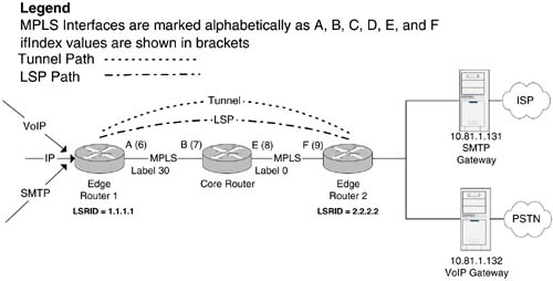
These are all fields in the IP packet header, as we saw in Chapter 3, "The Network Management Problem," Figure 3-5. Another object, called the action pointer, serves to point at an entry in either the LSR MIB ( mplsXCEntry ) or the TE MIB ( mplsTunnelEntry ). The mplsFTNMapTable is used to activate or map FTN entries defined in mplsFTNTable to specific interfaces. FTN entries are compared with incoming packets in the order in which they are applied on an interface. The mplsFTNMapTable supports a linked-list structure of FTN entries. The order of this list dictates the order of application of the associated policies on a given interface. So, if two FTNs, ftn1 and ftn2, are associated with an interface, then IP packets are processed against the settings in ftn1 and then ftn2. Finally, the mplsFTNPerfTable provides performance counters for each FTN entry on a per-interface basis. Because LERs are located at the boundary of IP and MPLS networks, the traffic levels can be very high (e.g., an SP boundary connected to a large corporate site), so there is a need for high-capacity counters in order to avoid 32-bit counters wrapping around (although wraparound is clearly still possible). Example Using the FTN MIBThis example illustrates the FTN MIB setup required for pushing MPLS-encoded IP traffic into either an LSP or a tunnel. Figure 9-2 illustrates two IP traffic streams feeding into an MPLS LER (Edge Router 1). One IP source is sending voice-over-IP (VoIP) telephony traffic, and the other is SMTP (email distribution). We want to push the SMTP traffic through the LSP and the VoIP traffic through the tunnel. The VoIP traffic has real-time requirements, so let's assume that we have created the tunnel with adequate bandwidth and an appropriate assigned QoS (as we saw in Chapter 8). The SMTP traffic requirements are less stringent, so we use an LSP for this purpose, with no bandwidth resource allocation and a best-effort QoS. The tunnel, however, has to carry real-time telephony data, so we assume that the tunnel has dedicated resources (e.g., 640kbps as we saw in Chapter 8). Figure 9-2. FTN MIB setup for incoming IP traffic. The LSP and tunnel are capable of transferring MPLS-encapsulated IP packets through the core network and delivering them as IP at the point of egress (Edge Router 2). In this case, we have two IP destinations: the SMTP Gateway at IP address 10.81.1.131 and a VoIP Gateway at 10.81.1.132, respectively. The setup we illustrate in Figure 9-2 is unidirectional (a telephony application would require bidirectional connections); to complete the VoIP picture, we would need another tunnel (or LSP) to forward traffic in the opposite direction. As can be seen in Figure 9-2, the egress MPLS label used by the core router has the reserved value 0. This value is called Explicit Null and is used in order to indicate to the next MPLS node (Edge Router 2) that the MPLS data must be stripped off the packet and a normal IP lookup performed. In other words, the label value of 0 tells the next node that the packet must be returned to the IP domain. The following example illustrates how the different IP traffic types are pushed into either the LSP or tunnel. Setting Up the mplsFTNTable for LSP RedirectionIn order to push IP traffic into the LSP in Figure 9-2, an entry is required in the mplsFTNTable . The LSP setup requires the network administrator to know in advance the values of the following objects at each hop:
Figure 9-2 illustrates the MIB objects needed for setting up the mplsFTNTable . These objects are required only for Edge Router 1 and consist of the following:
Given these details, we now have enough information to populate a row in mplsFTNTable : { mplsFTNIndex = 1, mplsFTNDescr = "FTN-ENTRY-1 for IP subnet 10.81.0.0", mplsFTNMask = 0x01, -- Look up destination address only mplsFTNAddrType = ipv4, mplsFTNDestIpv4AddrMin = 10.81.1.131, mplsFTNDestIpv4AddrMax = 10.81.1.131, mplsFTNActionType = redirectLsp, mplsFTNActionPointer = mplsXCLspId.5.0.0.3 } The value of mplsFTNActionPointer indicates the LSP to which packets should be redirected. It is set to point to the first column object of the XC entry that corresponds to this LSP. This is mplsXCIndex.5.0.0.3 , which represents the following mplsXCTable entry: { mplsXCIndex = 5, mplsInSegmentIfIndex = 0, -- originating LSP mplsInSegmentLabel = 0, -- originating LSP mplsOutSegmentIndex = 3, -- pointer to a row in mplsOutSegmentTable mplsXCLabelStackIndex = 0 } This mplsXCTable entry in turn points to the following row in the mplsOutSegmentTable : { mplsOutSegmentIndex = 3, mplsOutSegmentIfIndex = 6, mplsOutSegmentPushTopLabel = true, mplsOutSegmentTopLabel = 30 -- Egress label value } As can be seen, the values in mplsOutSegmentTable match those illustrated in Figure 9-2. Finally, we have mplsFTNMapTable , which activates the FTN entry: { mplsFTNMapIfIndex = 1, mplsFTNPrevIndex = 0, -- The first FTN entry on this interface mplsFTNMapCurrIndex = 1 } IP packets with the destination address 10.81.1.131 are now redirected into the LSP as required. Setting Up the mplsFTNTable for Tunnel RedirectionIn order to push IP traffic into the Tunnel in Figure 9-2, another entry is required in the mplsFTNTable . We give this row the index value 2. { mplsFTNIndex = 2, mplsFTNDescr = "FTN-ENTRY-2 for IP subnet 10.81.0.0", mplsFTNMask = 0x01, -- Look up destination address only mplsFTNAddrType = ipv4, mplsFTNDestIpv4AddrMin = 10.81.1.132, mplsFTNDestIpv4AddrMax = 10.81.1.132, mplsFTNActionType = redirectTunnel, -- We assume that the ingress and egress LSR IDs are 1.1.1.1 and -- 2.2.2.2 respectively for this tunnel as seen in Figure 92 mplsFTNActionPointer = mplsTunnelIndex.4.0.1.1.1.1.2.2.2.2 } In mplsTunnelTable , we have the following row with index 4: { mplsTunnelIndex = 4, mplsTunnelInstance = 0, -- primary tunnel mplsTunnelIngressLSRID = 1.1.1.1, mplsTunnelEgressLSRID = 2.2.2.2 } Finally, we have mplsFTNMapTable , which activates the FTN entry: { mplsFTNMapIfIndex = 1, mplsFTNPrevIndex = 1, mplsFTNMapCurrIndex = 2 } IP packets with the destination address 10.81.1.132 are now redirected into the traffic-engineered tunnel as required. |
EAN: 2147483647
Pages: 150