2.3 From network to fully unattended installation
| < Day Day Up > |
| Installing more than a few nodes from CD-ROM is not practical. The process of deploying SLES 8 or RHAS 3 on a large number of cluster nodes needs to be made faster and simpler, and you can accomplish this through network installation. There are many advantages to network installation:
However, network installation requires additional setup time to configure and operate an installation server. It is also potentially more expensive, as you need to have a system at hand that plays the role of this installation server. However, this system can be quite basic. Unlike AIX, which needs an AIX NIM install server, Linux can be network-installed from any UNIX or Linux system. We have installed Linux on LPARs from a laptop running Linux. The HMC itself has everything required to become a network installation server, but this is not supported. CSM provides a very effective way of managing network installations. In the following sections, we describe what happens under the cover when CSM drives network installations. Also, even if you do not wish to use CSM, you may still wish to benefit from network installation. 2.3.1 Network installation fundamentalsThe Linux Documentation Project [5] is an invaluable source of information for Linux. A few How-Tos relate to network boot and network installation. We recommend reading the following documentation:
Under SLES 8, the HowTos are packaged in the howtoenh package and reside under the /usr/share/doc/howto directory. Here we describe the steps needed to set up a network installation server to install SLES 8 or RHAS 3. Although we refer to "the" installation server, this function can be fulfilled jointly by three different systems. As we will see, we need a BOOTP/DHCP server, a TFTP server, and a NFS server to hold the packages to be installed. This NFS server does not need to be the BOOTP/DHCP or the TFTP server, although this is common practice. If you install a large cluster (100+ nodes), it might be judicious to use a few NFS servers to share the load and speed up the overall installation process. The network installation proceeds as follows :
Enabling network boot on pSeries serversA pSeries system can be instructed to boot from the network from the SMS menu. The menu for remote IPL is shown in Example 2-10. Example 2-10. Remote IPL menu Version RG030909_d65e03_sfw134 SMS 1.3 (c) Copyright IBM Corp. 2000,2003 All rights reserved. ------------------------------------------------------------------------------- Main Menu 1. Select Language 2. Password Utilities NOT available in LPAR mode 3. View Error Log 4. Setup Remote IPL (Initial Program Load) 5. Change SCSI Settings 6. Select Console NOT available in LPAR mode 7. Select Boot Options ------------------------------------------------------------------------------- Navigation Keys: X = eXit System Management Services ------------------------------------------------------------------------------- Type the number of the menu item and press Enter or select Navigation Key: 4 Selecting 4 in the menu shown in Example 2-10 on page 51 gives the list of network interface cards available for netbooting (or remote IPL, in pSeries terminology). This is a fast way to get the hardware addresses (MAC) of the adapters that you can use for network boot. Make a note of the MAC addresses, as these will be needed to configure the BOOTP/DHCP server later. An example is given in Example 2-11. Example 2-11. Adapters available for network bootVersion RG030909_d65e03_sfw134 SMS 1.3 (c) Copyright IBM Corp. 2000,2003 All rights reserved. ------------------------------------------------------------------------------- NIC Adapters Device Slot Hardware Address 1. 10/100 Mbps Ethernet PCI Adapt 5:U0.1-P2-I5/E1 0002556f1fef There are two other settings that we need to check for the adapter: the speed and duplex mode, and the spanning tree protocol. Select the adapter and you will be entering the network parameters for this network interface card as shown in Example 2-12. Example 2-12. Network parameters Version RG030909_d65e03_sfw134 SMS 1.3 (c) Copyright IBM Corp. 2000,2003 All rights reserved. ------------------------------------------------------------------------------- Network Parameters 10/100 Mbps Ethernet PCI Adapter II: U0.1-P2-I5/E1 1. IP Parameters 2. Adapter Configuration 3. Ping Test ------------------------------------------------------------------------------- Navigation keys: M = return to Main Menu ESC key = return to previous screen X = eXit System Management Services ------------------------------------------------------------------------------- Type the number of the menu item and press Enter or select Navigation Key: 1 We selected option 2: Adapter Configuration, as shown in Example 2-12 on page 52. This gave us the screen shown in Example 2-13. Example 2-13. Adapter Configuration menu Version RG030909_d65e03_sfw134 SMS 1.3 (c) Copyright IBM Corp. 2000,2003 All rights reserved. ------------------------------------------------------------------------------- Adapter Configuration 10/100 Mbps Ethernet PCI Adapter II: U0.1-P2-I5/E1 1. Speed,Duplex 2. Spanning Tree Enabled 3. Protocol ------------------------------------------------------------------------------- Navigation keys: M = return to Main Menu ESC key = return to previous screen X = eXit System Management Services ------------------------------------------------------------------------------- Type the number of the menu item and press Enter or select Navigation Key: 2 Set the speed and duplex as required. We chose 100 Mbit, full duplex in our case; see Example 2-14. Example 2-14. Speed and duplex settings Version RG030909_d65e03_sfw134 SMS 1.3 (c) Copyright IBM Corp. 2000,2003 All rights reserved. ------------------------------------------------------------------------------- Speed,Duplex 10/100 Mbps Ethernet PCI Adapter II: U0.1-P2-I5/E1 1. auto,auto ( rj45 ) 2. 10,half ( rj45 ) 3. 10,full ( rj45 ) 4. 100,half ( rj45 ) 5. 100,full ( rj45 ) ------------------------------------------------------------------------------- Navigation keys: M = return to Main Menu ESC key = return to previous screen X = eXit System Management Services ------------------------------------------------------------------------------- Type the number of the menu item and press Enter or select Navigation Key: 5 Moving back to the Adapter Configuration menu, select the spanning tree option and disable it, as shown in Example 2-15. The spanning tree protocol is described at the following Web site: http://www.cisco.com/univercd/cc/td/doc/product/rtrmgmt/sw_ntman/cwsimain/cwsi2/cwsiug2/vlan2/stpapp.htm This is a link-level management protocol designed to avoid loops in Ethernet networks. With the Ethernet configurations that you are likely to use, this is not needed; if you do not disable it now, every network boot will take 60 seconds to build the spanning tree before actually going to the BOOTP/DHCP server. Example 2-15. Spanning tree currently enabled, so disable it Version RG030909_d65e03_sfw134 SMS 1.3 (c) Copyright IBM Corp. 2000,2003 All rights reserved. ------------------------------------------------------------------------------- Spanning Tree Enabled 10/100 Mbps Ethernet PCI Adapter II: U0.1-P2-I5/E1 1. Yes <=== 2. No ------------------------------------------------------------------------------- Navigation keys: M = return to Main Menu ESC key = return to previous screen X = eXit System Management Services ------------------------------------------------------------------------------ Type the number of the menu item and press Enter or select Navigation Key: 2 BOOTP/DHCP serverYou need to define such a server on your network and it must be accessible either directly or through a gateway by the nodes you target for installation. If your installation server is a Linux server, you probably will end up defining a DHCP server. In the case of an AIX server, it is likely that you will create a BOOTP server. Both work in approximately the same way, but their configurations differ . DHCP is backward-compatible with BOOTP, whereas pSeries systems emit BOOTP requests . The BOOTP and DHCP protocols are described in: http://www.faqs.org/rfcs/ BOOTP configuration (for AIX)Under AIX, the BOOTP configuration resides in /etc/ bootptab . In our example, this file would contain a line like the one highlighted in Example 2-16. Example 2-16. Entry in the /etc/bootptab file# /etc/bootptab: database for bootp server (/usr/sbin/bootpd) # Blank lines and lines beginning with '#' are ignored. # # Legend: # # first field -- hostname # (may be full domain name and probably should be) # # hd -- home directory # bf -- bootfile # sa -- server IP address to tftp bootfile from # gw -- gateways # ha -- hardware address # ht -- hardware type # ip -- host IP address # sm -- subnet mask lpar8:hd=/tftpboot:bf=install:ip=192.168.100.84:ht=etherne:sa=192.168.100.110:g w=192.168.100.110:sm=255.255.255.0:ha=0002556f1fef What is important here is the hardware address (ha field). The hd and bf options are discussed in "The TFTP server" on page 57. Remember that the bootp server is configured in the /etc/inetd.conf file. You should see a line similar to the one shown in Example 2-17. Example 2-17. bootp server entry in /etc/inetd.confbootps dgram udp wait root /usr/sbin/bootpd bootpd /etc/bootptab The bootpd server can be started manually, outside of inetd, and in debug mode with the command shown in Example 2-18 on page 56. Make sure you remove bootp from the inetd configuration before running in standalone mode. Example 2-18. bootpd started manually# vi /etc/inetd.conf (to disable it in /etc/inetd.conf) # refresh -s inetd (tell inetd to reread its config file) 0513-095 The request for subsystem refresh was completed successfully. # /usr/sbin/bootpd -s -d -d -d -d -d /etc/bootptab BOOTPD: bootptab mtime is Sat Nov 8 22:33:43 2003 BOOTPD: reading "/etc/bootptab" BOOTPD: read 8 entries from "/etc/bootptab" BOOTPD: dumped 8 entries to "/etc/bootpd.dump". DHCP configuration (for Linux)DHCP has more features than BOOTP, and its configuration is slightly more complex. The configuration file for DHCP is /etc/dhcpd.conf. A description is given in Example 2-19. Example 2-19. Sample /etc/dhcpd.conf file always-reply-rfc1048 true; #deny unknown-clients; not authoritative; ddns-update-style ad-hoc; default-lease-time 60000; max-lease-time 720000; subnet 192.168.100.0 netmask 255.255.255.0 { range 192.168.100.77 192.168.100.84; option routers 192.168.100.60; group { next-server 192.168.100.110; host lpar8 { fixed-address 192.168.100.84; hardware ethernet 00:02:55:6f:1f:ef; filename "install"; option root-path "/install/sles"; } } } The DHCP server in SLES 8 comes with the dhcp-server RPM. It is started on SLES 8 with the rcdhcpd command. The startup script has built-in syntax checking for the DHCP configuration file. The messages from the DHCP server are directed to the /var/log/messages file. Sample output is given in Example 2-20. Example 2-20. DHCP server messagesNov 8 08:44:14 p630sles dhcpd: DHCPREQUEST for 192.168.100.84 from 00:02:55:6f:1f:ef via eth0 Nov 8 08:44:14 p630sles dhcpd: DHCPACK on 192.168.100.84 to 00:02:55:6f:1f:ef via eth0 The TFTP serverThe next step is to set up a Trivial File Transfer Protocol (TFTP) server that will deliver the boot file to the requesting node. The default directory for serving TFTP files is /tftpboot. For SLES 8, the boot file to copy to the /tftpboot directory is the install file at the root of the SLES 8 CD1. For RHAS 3, the file to be use is the netboot.img file found under images directory in the first CD of RHAS 3. By default, the files served by the TFTP server need to be placed under the /tftpboot directory. This directory and the files underneath should belong to a regular user. We use the tftpd:tftpd user in SLES 8, and set the permissions to 440 for the boot file. As reported [12] by Rolf Brudeseth at <rolfb@us.ibm.com>, you may experience problems during the TFTP download phase. As he suggests, the problems disappear when hardcoding the Address Resolution Protocol (ARP) address of the calling node on the installation server. This is done using the arp command, as shown in Example 2-21.
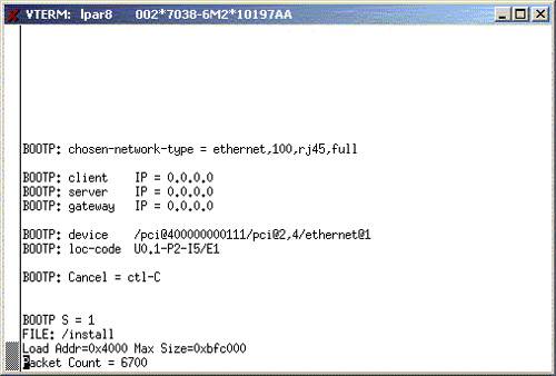
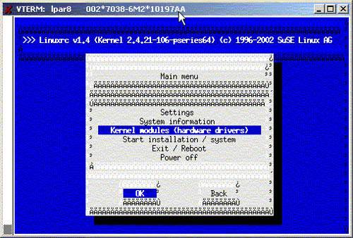
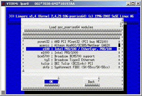
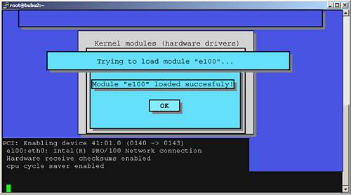
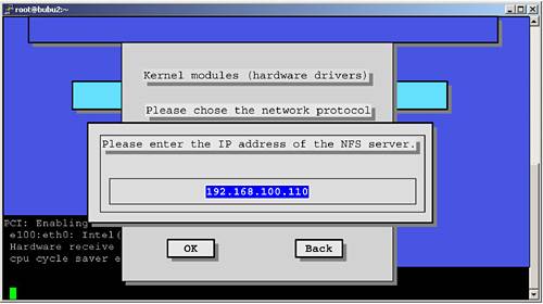
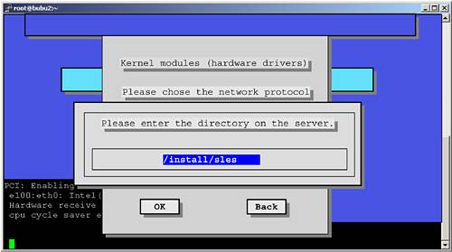
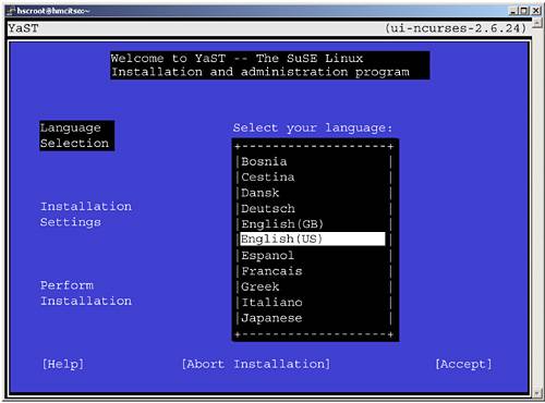
Example 2-21. Forcing a static entry in the ARP table# arp -s lpar8 00:02:55:6f:1f:ef # arp -a lpar3 (192.168.100.79) at 00:02:55:3A:06:19 [ether] on eth0 lpar1 (192.168.100.77) at 00:02:55:3A:06:8C [ether] on eth0 hmc (192.168.100.109) at 00:02:55:E1:18:30 [ether] on eth0 lpar8 (192.168.100.84) at 00:02:55:6F:1F:EF [ether] PERM on eth0 lpar5 (192.168.100.81) at 00:02:55:3A:06:2C [ether] on eth0 bubu2 (192.168.100.60) at 00:02:55:E4:5A:F4 [ether] on eth0 lpar4 (192.168.100.80) at <incomplete> on eth0 lpar7 (192.168.100.83) at 00:02:55:3A:07:DB [ether] PERM on eth0 lpar6 (192.168.100.82) at 00:02:55:6F:1C:35 [ether] PERM on eth0 ARP tables are usually of limited size . It is recommended that you remove the static entry from the ARP table, once the node has been installed. Also, we learned that the bootfile in the /tftpboot directory should not be larger than 8 MBytes or it will not boot. This could be a firmware limitation that does not allow for enough memory to store and start the boot file. On SLES 8, the tftp daemon is started from inetd. By default inetd is not enabled on a SLES 8 installation, so be sure to start inetd before attempting network installations. To check the correct operation of the TFTP server, you can try to download files off the server from another location or even from the server itself. This is accomplished by using the tftp command, as shown in Example 2-22. If the TFTP server cannot start for some reason, the get command hangs . Example 2-22. Check the TFTP serverroot@p630sles:/root # tftp p630sles tftp> bin tftp> get install Received 5194127 bytes in 0.4 seconds tftp> quit root@p630sles:/root # ls -l /tftpboot/install -r--r----- 1 tftpd tftpd 5194127 Nov 2 15:47 /tftpboot/install The NFS serverSetting up an NFS server for installation is very easy. Prepare a directory on which to download the base level CDs of your distribution, copy over the contents of the CDs in the same tree, and then export the whole directory. Make sure the permissions of the files and directories allow for anyone to read, and try mounting the exported directory on another system. Here we describe the Linux way of setting up the NFS server. If using AIX, make the appropriate changes. For SLES 8, we used the commands shown in Example 2-23 on page 59. We use downloaded ISO files of the SLES 8 distribution, and we use the Linux loop mount option. Keep the update CDs from SLES 8 away from this directory; only the base level CDs should go there. We describe in 2.5.2, "Applying SLES 8 patches" on page 88, how to upgrade the system with patch CDs. Example 2-23. Creating the NFS source directory ~# mkdir /install/sles ~# mkdir /mnt/sles8 ~# for i in 1 2 3 do mount -o loop -t iso9660 /tmp/SLES8-CD${i}.iso /mnt/sles8 cd /mnt/sles8 tar cf - . (cd /install/sles;tar xf -) cd umount /mnt/sles8 done We NFS export the directory by creating an entry in the /etc/exports file as shown in Example 2-24. Example 2-24. /etc/exports ~# cat /etc/exports /install *(ro,root_squash,sync) To start NFS on SLES 8, make sure the nfs- utils package is installed. The NFS server needs to be started with the nfsserver startup script under /etc/init.d. You may have to start the port mapper too, with the portmap startup script in the same directory. To check the correct operation of the NFS server, try to NFS-mount the target directory on another system, or at least on the server itself. 2.3.2 A practical exampleWe now perform our first network installation. We must first check that the DHCP server is running with the configuration file listed in Example 2-19 on page 56, and that the inetd superserver is started and configured to start the TFTP daemon upon request. We also have all the base level CDs dumped into a directory that is NFS-exported. First the system is set to boot from network in SMS. We need to copy an install kernel from the distribution to the /tftpboot directory. The base distribution contains a kernel called install, but we will use the latest installation kernel at hand. We use the one that comes with the patch CD (SP3, in our case), and copy it to the /tftpboot directory. Why do we do that? Because it is very likely that the newer kernels will do a better job at detecting the hardware. And note that we only extract the kernel from the SP3 CD; we do not use the RPMs from SP3. When the network boot starts, the terminal connection displays the BOOTP and TFTP progress as shown in Figure 2-30 on page 60. Figure 2-30. BOOTP followed by the TFTP transfer of the boot file Meanwhile, on the installation server, the system log reports the BOOTP and the TFTP requests as shown in Example 2-25. Example 2-25. /var/log/messagesNov 8 22:12:32 p630sles dhcpd: BOOTREQUEST from 00:02:55:6f:1f:ef via eth0 Nov 8 22:12:32 p630sles dhcpd: BOOTREPLY for 192.168.100.84 to lpar8 (00:02:55:6f:1f:ef) via eth0 Nov 9 03:12:32 p630sles in.tftpd[29604]: RRQ from 192.168.100.84 filename /install Once the kernel transferred has been started, it passes control to the /linuxrc scripts to start interacting with the user. Figure 2-31 on page 61 shows the first screen. Figure 2-31. linuxrc takes control So why can't linuxrc find the SLES 8 Installation CD? All three CDs have been downloaded in the /install/sles directory on the server and the dhcpd.conf file contains the root-path option to specify which root directory to use. The problem is that the Open Firmware driving the BOOTP request does not know how to retrieve kernel parameters from DHCP, store them, retrieve the kernel from TFTP, and start it with the command line arguments saved previously. In our case, the minimum arguments to start the kernel would be the kernel module for the network adapter, the NFS server IP address, and the directory to mount from this NFS server. When the installation kernel was started, it did not get this information, so linuxrc is prompting us to input the data. CSM solves this problem by entering the Open Firmware and passing the arguments directly to the kernel. Refer to "Passing the autoyast arguments to the kernel" on page 74 for an explanation of how to solve this problem in a different and very powerful way. For the time being, we have to interact with linuxrc to get the installation going. Pressing OK in the screen shown in Figure 2-31 takes us back to the first linuxrc screen shown in Figure 2-32 on page 62. From this screen, we must first load the Ethernet kernel module. Select Kernel modules (hardware drivers) as shown, and then select Load ppc_pseries64 modules . Figure 2-32. Top level installation screen Choose the network module for your Ethernet adapter from the list shown in Figure 2-33 on page 63. Figure 2-33. List of available network modules The module is then loaded, as shown in Figure 2-34 on page 64. Figure 2-34. Network module is loaded You have the choice for configuring the network adapter between fixed IP or DHCP. We used the DHCP method. linuxrc is cleverer than the Open Firmware, and it will retrieve not only the IP address but also the root-path option so that when we move on to configuring the source of the installation packages with NFS, linuxrc will fill in itself the fields with the information we entered in the /etc/dhcpd.conf file. Back at the top level installation screen shown in Figure 2-32 on page 62, we can now select the Start the installation/update field. We select the network installation method with the NFS protocol, and we confirm the choice of the NFS server in Figure 2-35 on page 65. Figure 2-35. NFS server address We confirm the name of the NFS server directory in Figure 2-36. This was filled at DHCP time, so we do not have to change it. Figure 2-36. NFS server directory After linuxrc mounts the root-path directory from the NFS server, it will load a large RAM disk (located in the boot/root file on the NFS server), switch to it, and start YaST2 off this new root directory, as shown in Figure 2-37. Figure 2-37. YaST2 takes control From then on, the screens are identical to the ones we describe in 2.2.1, "SLES 8 installation" on page 26. Tips
Congratulations, at this point, you have performed you first network installation of SLES 8. The process for RHAS 3 is very similar. The RHAS 3 does not use the information about the root-path option in /etc/dhcpd.conf, so you have to manually enter the IP address of the NFS server and the directory to mount. 2.3.3 Unattended installationNow there are no more CDs to insert, because the installation proceeds using the network only. You can try different installer kernels very easily, since there is no need to burn bootable CDs; such is the power of network installation. Still, we have to enter some information to drive the installation process, so the next step is to automate the network installation process: fill in the information one time, press Enter, and then let the systems install themselves . There are basically two ways of doing this:
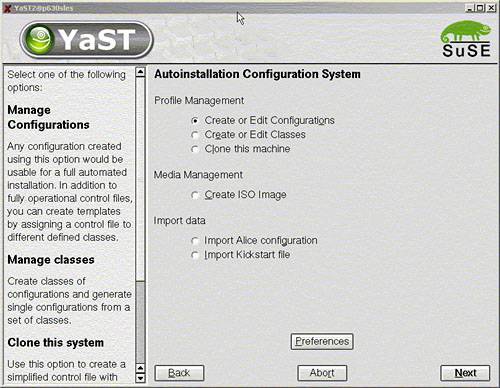
In this document, we only discuss using autoyast2 and kickstart. SuSE and RedHat each feature a specific tool to performed unattended network installation. Today, CSM for Linux on pSeries uses autoyast2; it will use kickstart when it supports RHAS 3. With CSM, the user does not interact directly with the automatic installation tools. But CSM expects the user to provide a control file that is then modified, mainly to add the RSCT management part in the custom post-installation script. In this section, we will use autoyast2 and kickstart directly to better understand how they work. This will be useful in helping you to troubleshoot any installation problems with CSM. Autoyast: the SuSE wayThe reference document for autoyast2, written by Anas Nashif, is located at http://www.suse.de/~nashif/autoinstall/8.1/autoyast2.pdf The idea is to write a control file that describes all the choices for the installation. This file is given as an argument to the installer program, which no longer requires user input as this control file contains all the necessary information. Broadly speaking, the autoyast2 file can contain information about:
The custom scripts can be use to tailor the installation. CSM uses this feature extensively to incorporate the newly installed node in the CSM cluster, but you can do anything you want in these scripts. They can be written in shell or in perl script. Control file formatThe autoyast2 control file is an XML file. This allows for easy parsing and syntax checking. You can use any editor to create the control file. Some syntactic editors (vim, emacs, kxmledit) can be used to check the proper structure of the file. Creating a control fileEach node to be installed can have its own control file. Example 2-26 shows an extract of a control file. Example 2-26. Excerpt of an autoyast2 control file<?xml version="1.0"?> <!DOCTYPE profile SYSTEM "/usr/share/YaST2/include/autoinstall/profile.dtd"> <profile xmlns="http://www.suse.com/1.0/yast2ns" xmlns:config="http://www.suse.com/1.0/configns"> <configure> <inetd> <inetd_services config:type="list"> <inetd_service> <service_name>ftp</service_name> <service_status>enable</service_status> </inetd_service> <inetd_service> <service_name>telnet</service_name> <service_status>enable</service_status> </inetd_service> </inetd_services> <start_inetd config:type="boolean">true</start_inetd> </inetd> To create a control file, you can either write it "from scratch" with an editor, or use theYaST2 administration tool: # yast2 autoyast This can be done on any system running SLES 8. The initial screen for autoyast is shown in Figure 2-38 on page 69. Figure 2-38. Autoyast configuration The cloning option is useful to quickly create a starting point. This option extracts the information from the running system and creates the corresponding autoyast2 file. If you have many identical systems, you could install one system manually, run yast2 autoyast on this node to create a control file, and then use this control file to install the remaining nodes. If you choose the first option, as shown in Example 2-38, you are guided to enter your choices manually. The "Classes" option can be used to organize your control files by families, for example using a control file for your "Web servers" and another one for "interactive nodes". It is recommended that you start with a simple control file that works, and then improve it. The file shown in Example 2-27 on page 70 is a very basic control file that installs a minimal system on the first SCSI disk using an Ethernet adapter configured with DHCP. The root password and the admin password are both set to itsoadmin and are encrypted. A very simplistic customization script is embedded in the file. It merely creates a file in /etc/profile.d directory to set the path to access the IBM XL Fortran compiler. In real situations, you would add more useful commands here, such as install additional software, create userids, set up LDAP, or whatever. Important If you create your own autoyast2 control file, be sure to set the "confirm config" flag to false in the <install><general><mode> section. This is not the default. Without this setting, the installation will not run fully automated. Example 2-27. Sample autoyast2 control file<?xml version="1.0"?> <!DOCTYPE profile SYSTEM "/usr/share/YaST2/include/autoinstall/profile.dtd"> <profile xmlns="http://www.suse.com/1.0/yast2ns" xmlns:config="http://www.suse.com/1.0/configns"> <configure> <networking> <dns> <dhcp_hostname config:type="boolean">false</dhcp_hostname> <dhcp_resolv config:type="boolean">false</dhcp_resolv> <domain>local</domain> <hostname>lpar8</hostname> </dns> <interfaces config:type="list"> <interface> <bootproto>dhcp</bootproto> <device>eth0</device> <module>e100</module> <startmode>onboot</startmode> <wireless>no</wireless> </interface> </interfaces> <routing> <ip_forward config:type="boolean">false</ip_forward> <routes config:type="list"> <route> <destination>default</destination> <device>-</device> <gateway>192.168.100.60</gateway> <netmask>-</netmask> </route> </routes> </routing> </networking> <scripts> <post-scripts config:type="list"> <script> <filename>custom</filename> <interpreter>shell</interpreter> <source> <![CDATA[# Very basic example of a custom script echo "export PATH=$PATH:/opt/ibmcmp/xlf/8.1/bin" > /etc/profile.d/xlf.sh ]]> </source> </script> </post-scripts> </scripts> <users config:type="list"> <user> <encrypted config:type="boolean">true</encrypted> <user_password>hRoWvYp76SFiU</user_password> <username>root</username> </user> <user> <encrypted config:type="boolean">true</encrypted> <user_password>3VBnRzl.nZu06</user_password> <username>admin</username> </user> </users> </configure> <install> <general> <clock> <timezone>US/Eastern</timezone> </clock> <keyboard> <keymap>english-us</keymap> </keyboard> <language>en_US</language> <mode> <confirm config:type="boolean">false</confirm> <forceboot config:type="boolean">false</forceboot> <interactive_boot config:type="boolean">false</interactive_boot> <reboot config:type="boolean">false</reboot> </mode> <mouse> <id>00_ps2</id> </mouse> </general> <partitioning config:type="list"> <drive> <device>/dev/sda</device> <initialize config:type="boolean">false</initialize> <partitions config:type="list"> <partition> <crypt_fs config:type="boolean">false</crypt_fs> <format config:type="boolean">false</format> <partition_id config:type="integer">65</partition_id> <partition_type>primary</partition_type> <size>4MB</size> </partition> <partition> <crypt_fs config:type="boolean">false</crypt_fs> <crypt_key></crypt_key> <format config:type="boolean">false</format> <mount></mount> <partition_id config:type="integer">130</partition_id> <partition_type>primary</partition_type> <size>1GB</size> </partition> <partition> <crypt_fs config:type="boolean">false</crypt_fs> <crypt_key></crypt_key> <filesystem config:type="symbol">reiser</filesystem> <format config:type="boolean">true</format> <mount>/</mount> <partition_id config:type="integer">131</partition_id> <partition_type>primary</partition_type> <size>512MB</size> </partition> <partition> <crypt_fs config:type="boolean">false</crypt_fs> <crypt_key></crypt_key> <format config:type="boolean">false</format> <mount></mount> <partition_id config:type="integer">142</partition_id> <lvm_group>system</lvm_group> <partition_type>primary</partition_type> <size>24GB</size> </partition> </partitions> <use>all</use> </drive> </partitioning> <lvm config:type="list"> <lvm_group> <lvm_name>system</lvm_name> <pesize>4M</pesize> <logical_volumes config:type="list"> <lv> <lv_name>usrlv</lv_name> <lv_size>8GB</lv_size> <lv_fs>reiser</lv_fs> <lv_mount>/usr</lv_mount> </lv> <lv> <lv_name>varlv</lv_name> <lv_size>512MB</lv_size> <lv_fs>reiser</lv_fs> <lv_mount>/var</lv_mount> </lv> <lv> <lv_name>homelv</lv_name> <lv_size>4GB</lv_size> <lv_fs>reiser</lv_fs> <lv_mount>/home</lv_mount> </lv> <lv> <lv_name>optlv</lv_name> <lv_size>1GB</lv_size> <lv_fs>reiser</lv_fs> <lv_mount>/opt</lv_mount> </lv> </logical_volumes> </lvm_group> </lvm> <software> <base>Minimal</base> </software> </install> </profile> At the time of writing, it is not possible to create LVM partitions with yast2 autoyast , and the control file must be edited manually to define the volume groups and the logical volumes . What we did is shown in Example 2-27 on page 70 in the <lvm></lvm> section. Also, if you run the same installation two times, the second installation complains that the volume group you are trying to create already exists and the installation prompts you to remove the previous volume group. To avoid this situation, Tobias Mucke [13] proposes using the script shown in Example 2-28 on page 74, to be inserted in the <scripts> section of the control file. Adjust the line giving the list of volume groups that could preexist on the system before installation starts.
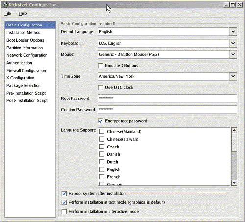
Use the script shown in Figure 2-28 on page 74. Example 2-28. Removing preexisting volume groups<pre-scripts config:type="list"> <script> <filename>/vgremove.sh</filename> <interpreter>shell</interpreter> <source> <![CDATA[ insmod lvm-mod vgscan # Adjust the list of VGs to be removed vgs=`echo /dev/system` for vg in $vgs do if [ -d $vg ] then vgchange -a y $vg lvs=`ls $vg` for lv in $lvs do i=`basename $lv` if [ $i != "group" ] then lvremove -f $vg/$i fi done vgchange -a n $vg vgremove $vg fi done ]]> </source> </script> </pre-scripts> Passing the autoyast arguments to the kernelTo start the autoyast2 network installation, the installation kernel retrieved from the /tftpboot directory must be given a few arguments which describe the name of the control file and its location. As discussed in 2.3.2, "A practical example" on page 59, TFTP cannot be used to pass arguments to the kernel; instead, we have to use the Open Firmware boot command. Open Firmware is described in greater detail in 2.4.3, "Open Firmware basics" on page 80 but at this point, we will use it as described in Example 2-29 on page 75. To start the unattended installation, we set the system to boot to Open Firmware, start it, and open a terminal window. When we get to the Open Firmware prompt, we enter the boot command shown in Example 2-29, all in one single line. This command tells the firmware to load a kernel from the network and start it with the command line starting at "insmod=e100" . This command line gives enough information to the kernel, to linuxrc in fact, to start the unattended installation. We specify the installation server and directory, as well as the location of the autoyast2 control file. From then on, the installation proceeds without user interaction. Example 2-29. Open Firmware boot command 1 = SMS Menu 5 = Default Boot List 6 = Stored Boot List 8 = Open Firmware Prompt memory keyboard network scsi speaker ok 0 > boot net insmod=e100 insmod=lvm-mod instmode=nfs install=nfs://192.168.100.110/install/sles autoyast=nfs://192.168.100.110/install/sles/trylvm.xml Tip SLES 8 SP3 comes with a very interesting tool that can "burn" command line arguments directly into a SuSE kernel, using a built-in static 512 characters . This is described in the ppc/netboot/ directory of the SP3 CD. To create a customized kernel for the unattended installation, copy the install kernel into the /tftpboot directory and issue: /tftpboot:# ...../sp3/ppc/netboot/mkzimage_cmdline -a 1 -c\ -s "insmod=e100 insmod=lvm-mod instmode=nfs \ install=nfs://192.168.100.110/install/sles \ autoyast=nfs://192.168.100.110/instal/sles/trylvm.xml" install This is very handy, because we do not have to go to Open Firmware any more. Just boot through TFTP and the kernel will start linuxrc with the right arguments. To recover a "neutral" kernel, simply run: /tftpboot:# mkzimage_cmdline -a 0 -c install This is a far-reaching utility, as it can be used to pass any kind of argument to the kernel. We also use it in "Disk setup" on page 364 to circumvent SCSI ID conflicts in HA environments. At the time of writing, RHAS 3 does not provide an equivalent utility. Kickstart: the Red Hat wayRed Hat's kickstart offers functionally similar to autoyast2. Here, the control file has no particular structure; it is simply a flat text file with directives. The easiest way to create a kickstart template file is to use redhat-config-kickstart. But although this is easy to use, it is not quite complete for kickstarting PowerPC systems; the control file, whose name defaults to ks.cfg, has to be manually edited. The main redhat-config-kickstart window is shown in Figure 2-39. It cannot run in text mode, but you can run it on any recent Red Hat system. Figure 2-39. redhat-config-kickstart The control file generated this way does not work as is. The partition table that would be generated would not contain a PReP boot partition, which is needed, and an error is generated when configuring X windows . In fact, the installer reports an error when trying to skip the X configuration even though it detected no graphical device. Fortunately, if you manually install an RHAS 3 system, a sample kickstart configuration file for the system that has just been installed is given in /root/anaconda-ks.cfg. Using this file and the one generated by the redhat-config-kickstart command, plus advice from Jeremy Katz [14] for the partitioning problems, we put together a ks.cfg file that would work for us. It is listed in Example 2-30.
Example 2-30. Sample ks.cfg#Generated by Kickstart Configurator # And a good deal of hand editing too!! #System language lang en_US #Language modules to install langsupport --default=en_US #System keyboard keyboard us #System mouse mouse none #Sytem timezone timezone America/New_York #Root password rootpw --iscrypted rTArc8M$Un3VRAb5rS204seG4pEtY1 #Reboot after installation reboot #Use text mode install text #Install Red Hat Linux instead of upgrade install #Use NFS installation Media nfs --server=192.168.100.110 --dir=/install/rhas #System bootloader configuration bootloader --location=partition --append console=hvc0 #Partition clearing information clearpart --all --initlabel #Disk partitioning information autopart #part None --fstype "PPC PReP Boot" --size 4 --asprimary #part / --fstype ext3 --size 8192 --asprimary #System authorization infomation auth --useshadow --enablemd5 #Network information network --bootproto=dhcp --device=eth0 --hostname lpar6 #Firewall configuration firewall --disabled #Do not configure XWindows #skipx #Package install information %packages @ base-x @ text-internet @ server-cfg @ dialup @ admin-tools @ graphical-internet @ compat-arch-support kernel yaboot %post Passing the kickstart argument to the kernelUnlike SLES 8, RHAS 3 does not provide a trick for burning command line arguments in the kernel, so we have to boot to Open Firmware, retrieve the kernel stored (netboot.img file from the images directory on RHAS 3 CD1) on the server in the /tftpboot directory, and then start it with the appropriate arguments. This is shown in Example 2-31. Note that the syntax for the location of the control file on NFS is different from SLES 8. Example 2-31. Kickstart command line arguments 1 = SMS Menu 5 = Default Boot List 6 = Stored Boot List 8 = Open Firmware Prompt memory keyboard network scsi speaker ok 0 > boot net ks=nfs:192.168.100.110:/install/rhas/ks.cfg SIS: the Open Source way, but not for pSeries yetSystem Installation Suite [15] (SIS) is an open source project that aims at providing a way to massively install Linux on similar nodes. Unlike autoyast2 or kickstart, where you specify the list of packages to be installed, SIS uses a concept very similar to that of mksysb in AIX.
One node, designated as a golden client, is primarily installed and customized. Some additional software could be installed or a kernel recompiled. Once the golden client is ready for replication, the client part of SIS is used to create a snapshot of the node. This snapshot (an AIX administrator would call it a mksys ), is moved onto a SIS server. On this server, a specific SIS kernel and initrd file are used to produce a bootable medium (CD-ROM) or set up an image to be used for network installation. SIS is supported by CSM on xSeries . Unfortunately, the network installation part is heavily dependent on the Pre eXecution Environment (PXE) from Intel , which is not used on pSeries. PXE is responsible for handling the dialog between a network interface card and a DHCP server, and is commonplace on IA32 and IA64 servers. There is more to SIS than the initial installation. It has useful features for quickly applying updates to a collection of nodes. However, the support for pSeries hardware is still embryonic. The client part is fairly hardware-independent and we were able to create an image of a pSeries node, but we could not get the server part to work properly. Stay tuned and watch for announcements on: http:// sourceforge .net/projects/systemimager/ |
| < Day Day Up > |
EAN: N/A
Pages: 108
- ERP Systems Impact on Organizations
- ERP System Acquisition: A Process Model and Results From an Austrian Survey
- Distributed Data Warehouse for Geo-spatial Services
- Data Mining for Business Process Reengineering
- Relevance and Micro-Relevance for the Professional as Determinants of IT-Diffusion and IT-Use in Healthcare
- Business Continuity Planning and Disaster Recovery Planning
- Physical (Environmental) Security
- Appendix B Glossary of Terms and Acronyms
- Appendix C The Information System Security Architecture Professional (ISSAP) Certification
- Appendix E The Information System Security Management Professional (ISSMP) Certification