Collaboration Diagrams
| I l @ ve RuBoard |
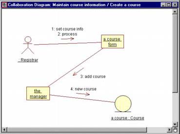
| A collaboration diagram is an alternate way to show a scenario. This type of diagram shows object interactions organized around the objects and their links to each other. A collaboration diagram contains
The UML notation for objects, links, and messages in a collaboration diagram is shown in Figure 5-10. CREATING COLLABORATION DIAGRAMS FROM SEQUENCE DIAGRAMS IN RATIONAL ROSE
Figure 5-10. UML Notation for Objects, Links, and Messages in a Collaboration Diagram The collaboration diagram is shown in Figure 5-11. Figure 5-11. Collaboration Diagram Collaboration diagrams can also be created from scratch. In that case, a sequence diagram can be created from the collaboration diagram by selecting the Browse:Create Sequence Diagram menu choice or by pressing the F5 key. |
| I l @ ve RuBoard |
EAN: 2147483647
Pages: 134