Developing Class Diagrams (Analysis)
| UML Class diagrams are imperative to any object-oriented design effort, as they provide the static design view of the solution system and the structure of the code that will be produced in the development effort. However, they can also be used in the Analysis phase, where they are aptly known as conceptual models . The objective of a conceptual model is to capture the concepts that need to be addressed by a system, the properties of those concepts, and how they are related . A byproduct of developing conceptual models is a greater understanding of a system's business context, because the captured concepts will be derived from the stakeholder's perspective and vocabulary. Because conceptual models are drafted in the Analysis phase, they will not be as rich as traditional Class diagrams, which will be discussed later in this chapter. However, they do provide a great foundation for the Class diagrams that will be produced in the Design phase. The Features of a Conceptual ModelThe idea behind conceptual modeling is to capture the primary concepts or ideas behind the solution system, with which the stakeholders must be familiar. Concepts can be derived directly from a system's requirements specification, for example by extracting the following candidate concepts:
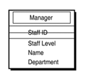
Note This list only provides examples of candidate concepts and should not be used as a complete reference for identifying concepts. Alternatively, concepts can be derived from facilitated workshops geared towards identifying concepts with the stakeholders. It is important to ensure the concepts that are identified have structural attributes that further describe the concept in the context of the stakeholder business environment. UML does not specify how you can develop conceptual diagrams; it only provides the notation to capture them, which is illustrated in Figure 3.13. Figure 3.13. The UML representation of a concept. Note A UML representation of a concept does not contain any associated behavior because it is more aligned with the design of a system rather than the analysis. Referencing Figure 3.13, an example of a Manager concept, including its attributes, is illustrated in Figure 3.14. Figure 3.14. An example of a Manager concept. Relationships between concepts in UML are expressed as a single line called an association . Each association has a descriptive name and a multiplicity (cardinality) that describes the number of instances a concept can participate in the relationship. The multiplicity is expressed as a number at the ends of an association using the following syntax:
For example, Figure 3.15 illustrates a relationship where one CEO concept manages one or more Director concepts. Figure 3.15. An example of an association between a CEO concept and a Director concept. When drawing a conceptual model, the best approach is to take one concept, identify all its associations and cardinalities with other concepts, and then move to the next concept and apply the same approach and so on. |
EAN: 2147483647
Pages: 360
- Step 2.1 Use the OpenSSH Tool Suite to Replace Clear-Text Programs
- Step 3.1 Use PuTTY as a Graphical Replacement for telnet and rlogin
- Step 3.4 Use PuTTYs Tools to Transfer Files from the Windows Command Line
- Step 5.2 Troubleshooting Common OpenSSH Errors/Problems
- Step 6.2 Using Port Forwarding Within PuTTY to Read Your E-mail Securely


