12.4 WIRELESS LOCAL LOOPS
|
| < Day Day Up > |
|
12.4 WIRELESS LOCAL LOOPS
For providing telecommunication facilities, the network elements required are the switch, the trunks, the local loops, and the subscriber terminals. The local loop is the dedicated link between the subscriber terminal and the switch. In cities and towns, the local loop uses twisted pair as the transmission medium because the distance between the switch and the subscriber terminal generally will be less than 5 km. Because the subscriber density is high in cities and towns, the cost of installing a switch for subscribers within a radius of 5 km is justified. In remote and rural areas, the subscriber density will be less, the number of calls made by the subscribers will not be very high, and the areas are separated by long distances from the nearby towns. As a result, laying a cable from one town to another is not cost effective. Installing a switch to cater to a small number of subscribers is also prohibitively costly.
In the telephone network, the local loop is the costliest network element. To provide telephone services to remote and rural areas, wireless local loop is the most cost-effective alternative.
Wireless local loops can be in two configurations. Figure 12.2 shows configuration 1. A radio base station will be connected to the switch. The base station is generally located in a town at the same premises as the switch. A number of remote stations communicate with the base station through radio. Each remote station can be installed in an area, and it can support anywhere between 1 and 32 telephones. The distance between the base station and each remote generally can be up to 30 km. A base station can provide telephone facilities to subscribers in a radius of 30 km. This configuration is used extensively for providing telephone facilities in rural and remote areas.
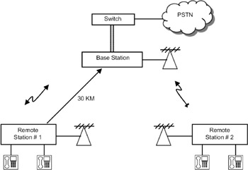
Figure 12.2: Wireless local loop configuration 1.
Wireless local loop can have two configurations. In one configuration, the subscriber telephone is connected to the switch using radio as the medium. In the other configuration, wireless connectivity is provided between the subscriber terminal and the distribution point, and the connectivity between the switch and the distribution point is through a wired medium.
Figure 12.3 shows configuration 2 of wireless local loops. In this configuration, a number of base stations are connected to the switch using cable. Each base station in turn communicates with a number of remote stations. Each remote station can support a number of telephones. In this configuration, the local loop is a combination of wired and wireless media. This configuration is used extensively in urban areas. TDMA and CDMA technologies are used in this configuration. The number of subscribers supported by the base station/remote station depends on the access technology. In the following sections, some representative wireless local loop systems are described.
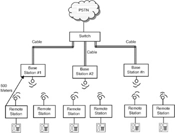
Figure 12.3: Wireless local loops configuration 2.
| Note | Wireless local loop also is gaining popularity in urban areas because of reduced installation and maintenance costs. |
12.4.1 Shared Radio Systems
The block diagram of a shared radio system is shown in Figure 12.4. This system can cater to a number of communities within a radius of about 30 km from the base station. The system consists of a base station and a number of remote stations (say, 15). Each remote station will provide one telephone connection. This remote telephone can be used as a public call office (PCO) to be shared by a number of people. The base station consists of a base station controller and a radio. The base station controller is connected to the PSTN through the switch located at a town. The base station radio will have transmitter /receivers for two radio channels. Both the channels can be used for either incoming or outgoing calls. So, the system works in the FDMA mode. When a remote user wants to make a call, one of the free channels will be assigned to him, with one uplink frequency and one downlink frequency. Since the base station can support only two radio channels at a time, only two remote telephones can use the system. This is not a major problem because the traffic in rural areas is not very high. This system is called a 2/15 shared radio system, 2 indicating the number of radio channels, and 15 indicating the number of remotes supported by the system. For each channel, 25kHz of bandwidth is allocated. These systems operate in the VHF (150MHz and 170MHz) and UHF (400MHz) bands. Shared radio systems are analog systems.
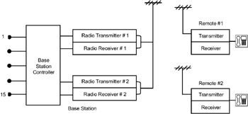
Figure 12.4: Shared radio system as wireless local loop.
This concept can be extended to develop higher order systems such as a 4/32 shared radio system, which will have 4 radio channels and 32 remotes, or an 8/64 shared radio system, which will have 8 radio channels and 64 remotes.
These systems also can support data services up to a data rate of 9.6kbps. Using normal line modems, the data can be sent in the voice channels.
In a shared radio system (SRS), a number of remote stations communicate via a central station. A few radio channels are shared by the remotes using Frequency Division Multiple Access. SRS provides low-cost analog wireless local loops.
12.4.2 Digital Local Loops
The digital wireless local loop using TDM/TDMA is shown in Figure 12.5. Unlike the shared radio systems, this system uses digital communication. The system consists of a base station and number of remotes (up to 64). The base station is connected to the switch using a T1 trunk (to support 24 voice channels). Each remote station can be connected to a small rural switch. The rural switch can handle up to 32 subscribers. The advantage of having a small switch is that the local calls within a community can be switched locally without the need for a radio. All the remotes will be within a radius of 30 km from the base station. Communication from the base to the remote will be in TDM mode, and from remote to the base will be in TDMA mode. The salient features of the system are as follows:
Frequency of operation: The system operates in the 800MHz frequency band. The base station transmits in the 840–867.5 MHz band (downlink frequency). The remote stations transmit in the frequency band 885–912.5 MHz band. The number of channels will be 12 with a channel spacing of 2.5MHz. The modulation in both directions can be QPSK. Alternatively, the base station can use FSK for transmission, and remote stations can use QPSK—this scheme has the advantage that the remote station electronics will be less complex because demodulation of FSK is much easier than demodulation of QPSK. Base station and the remote stations transmit a power of 2 watts. The base station uses an omni-directional antenna, and the remote stations use directional antennas.
Voice coding: To conserve the spectrum, ADPCM can be used for voice coding. In ADPCM, the voice is coded at 32kbps.
Access scheme: The base station transmits the data in TDM mode. The data for all the remote stations will be multiplexed, and the multiplexed data will be broadcasted. All the remote stations will receive the data, and each remote will decode the data only if the data is meant for it by matching the received address with its own address.
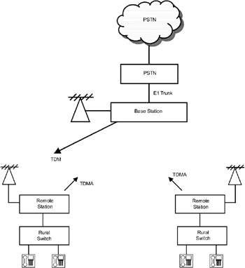
Figure 12.5: Digital wireless local loop using TDM/TDMA.
The remote stations will use the TDMA for accessing the base station. Each remote will be assigned a time slot and transmit the data in that time slot.
Assignment of TDMA slots: Since there is less traffic in rural areas, fixed assignment of time slots results in wasted time slots because even if there is no call, the slot will be assigned to that remote. In dynamic TDMA, each remote will get a time slot periodically that is exclusively for signaling. When a subscriber at a remote picks up the telephone and dials a telephone number to make a call, a request for a voice slot is sent to the base station along with the called number. The base station checks for the availability of the called party. If available, a time slot is allocated in which the remote can send the digitized voice.
Frame and slot sizes: There is a trade-off between buffer storage required and synchronization overhead. If the frame size is small, the synchronization overhead will be high; if the frame size is large, buffer storage requirement will be high. As an optimal choice, 8 msec can be used as the frame size.
The TDM/TDMA frame formats are shown in Figure 12.6. From base to remote, the 8 msec frame consists of a signaling slot of 416 bits and 27 voice slots of 288 bits. From the remote to the base, the signaling slot is also 418 bits and voice slot 288 bits. The voice slot contains 12 bits of guard time, 20 bits of preamble and sync, and 256 bits of 32 kbps ADPCM voice data. The guard time is used to take care of the propagation delay. The preamble and sync bits are for synchronization. Since the frame has 27 time slots, 27 subscribers connected to different remote stations can make calls simultaneously.
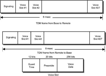
Figure 12.6: TDM/TDMA frame formats.
Because the base transmits the data in broadcast mode, all the remotes can receive the data. Each remote synchronizes itself using the synchronization pattern and processes only the signaling slot data and the voice slots allocated to it. The remaining slots are ignored. The remote communicates with the base in the channel allocated to it for signaling. This type of signaling is called common channel signaling because a separate slot is used for signaling, and the voice slots contain only voice data and no signaling information.
Digital local loops using the TDM/TDMA technique provide wireless connectivity between a number of remote stations and a central station. The central station transmits the data in TDM broadcast mode, and the remote stations use TDMA slots to send their data.
The digital wireless local loop systems based on TDM/TDMA provide very low cost solutions for rural/ sub-urban areas. Hughes Network Systems, USA, SR Telecom, Canada, and Japan Radio Company, Japan are the major organizations that developed such systems.
| Note | In the TDM/TDMA time slots, a separate slot is dedicated for carrying signaling information. This is known as common channel signaling. |
|
| < Day Day Up > |
|
EAN: 2147483647
Pages: 313