7.3 TIME DIVISION MULTIPLEXING
|
| < Day Day Up > |
|
7.3 TIME DIVISION MULTIPLEXING
In synchronous time division multiplexing (TDM), the digitized signals are combined and sent over the communication channel. Consider the case of a communication system shown in Figure 7.4. Three data sources produce data at 64kbps using pulse code modulation (PCM). Each sample will be 8 bits, and the time gap between two successive samples is 125 microseconds. The job of the MUX is to take the 8-bit sample value of the first channel and the 8 bits of the second channel and then the 8 bits of the third channel. Again, go back to the first channel. Since no sample should be lost, the job of the MUX is to complete scanning all the channels and obtain the 8-bit sample values within 125 microseconds. This combined bit stream is sent over the communication medium. The MUX does a scanning operation to collect the data from each data source and also ensures that no data is lost. This is known as time division multiplexing. The output of the MUX is a continuous bit stream, the first 8 bits corresponding to Channel 1, the next 8 bits corresponding to Channel 2, and so on.
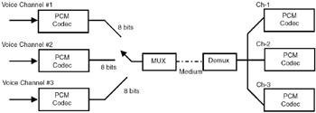
Figure 7.4: Time division multiplexing.
In time division multiplexing, the digital data corresponding to different sources is combined and transmitted over the medium. The MUX collects the data from each source, and the combined bit stream is sent over the medium. The DEMUX separates the data corresponding to the individual sources.
In a telephone network, switches (or exchanges) are interconnected through trunks. These trunks use TDM for multiplexing 32 channels. This is shown in Figure 7.4. The 32 channels are, by convention, numbered as 0 to 31. Each channel produces data at the rate of 64kbps. The MUX takes the 8 bits of each channel and produces a bit stream at the rate of 2048kbps (64kbps × 32). At the receiving end, the DEMUX separates the data corresponding to each channel. The TDM frame is also shown in Figure 7.5. The TDM frame depicts the number of bits in each channel. Out of the 32 slots, 30 slots are used to carry voice and two slots (slot 0 and slot 16) are used to carry synchronization and signaling information.
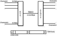
Figure 7.5: Time division multiplexing of voice channels.
Though TDM appears very simple, it has to be ensured that the MUX does not lose any data, and hence it has to maintain perfect timings. At the DEMUX also, the data corresponding to each channel has to be separated based on the timing of the bit stream. Hence, synchronization of the data is very important. Synchronization helps in separating the bits corresponding to each channel. This TDM technique is also known as synchronous TDM.
In the Public Switched Telephone Network (PSTN), the switches are interconnected through trunks that use TDM. Trunks in which 30 voice channels are multiplexed are called E1 trunks.
The trunks used in the telephone network using this TDM mechanism are known as T1 trunks or T1 carriers. The multiplexing of 24 channels is known as Level 1 multiplexing. Four such T1 carriers are multiplexed to form T2 carrier. Seven T2 carriers are multiplexed to form T3 carrier and six T3 carriers are multiplex to form T4 carriers. The various levels of multiplexing, the number of voice channels and the data rates are given in Table 7.1. Note that at each level, additional bits are added for framing and synchronization.
| Level | Number of Voice Channels | Data Rates (Mbps) |
|---|---|---|
| 1 | 24 | 1.544 |
| 2 | 96 | 6.312 |
| 3 | 672 | 44.736 |
| 4 | 4032 | 274.176 |
| Note | In a T1 carrier, the total number of voice channels is 24—there are 24 voice slots in the TDM frame. In Europe, a different digital hierarchy is followed. At the lowest level, 30 voice channels are multiplexed and the trunk is called E1 trunk. |
7.3.1 Statistical Time Division Multiplexing
In the TDM discussed above, each data source is given a time slot in which the data corresponding to that source is carried. If the data source has no data to transmit, that slot will be empty. To make best use of the time slots, the data source can be assigned a time slot only if it has data to transmit. A centralized station can assign the time slots based on the need. This mechanism is known as statistical time division multiplexing (STDM).
In STDM, the data source is assigned a time slot only if it has data to transmit. As compared to synchronous TDM, this is a more efficient technique because time slots are not wasted.
|
| < Day Day Up > |
|
EAN: 2147483647
Pages: 313