Chapter 5: Error Detection and Correction
|
| < Day Day Up > |
|
In a digital communication system, totally error-free transmission is not possible due to transmission impairments. At the receiving end, there should be a mechanism for detection of the errors and if possible for their correction. In this chapter, we will study the various techniques used for error detection and correction.
5.1 NEED FOR ERROR DETECTION AND CORRECTION
Consider a communication system in which the transmitted bit stream is
1 0 11 0 111 0
The transmitted electrical signal corresponding to this bit stream and the received waveform are shown in Figure 5.1. Due to the noise introduced in the transmission medium, the electrical signal is distorted. By using a threshould, the receiver determines whether a 1 is transmitted or a 0 is transmitted. In this case, the receiver decodes the bit stream as
1 0 1 0 0 1 0 1 0
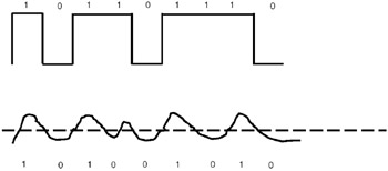
Figure 5.1: Errors introduced by transmission medium.
In a digital communication system, some bits are likely to be received in error due to the noise in the communication channel. As a result, 1 may become 0 or 0 may become 1. The Bit Error Rate (BER) is a parameter used to characterize communication systems.
At two places, the received bit is in error—1 has become 0 in both places.
How many errors can be tolerated by a communication system? It depends on the application. For instance, if English text is transmitted, and a few letters are received in error, it is tolerable. Studies indicate that even if 20% of the letters are missing, human beings can understand the text.
Suppose the communication system is used to transmit digitized voice from one place to another. Studies indicate that even if the Bit Error Rate is 10−3, the listener will be able to understand the speech. In other words, a voice communication system can tolerate one error for every 1000 bits transmitted.
| Note | The performance of a communication system can be characterized by the Bit Error Rate (BER). If BER is 10−3, there is one error per 1000 bits. |
Now consider the case of a banking application. Suppose I need to transfer $100 from my account to a friend's account through a data communication network. If the digit 1 becomes 3 due to one bit error during transmission, then instead of $100, $300 will be deducted from my account! So, for such applications, not even a single error can be tolerated. Hence, it is very important to detect the errors for data applications.
Errors can be classified as random errors and burst errors. Random errors, as the name implies, appear at random intervals. Burst errors are caused by sudden disturbances such as lightning. Such disturbances cause many consecutive bits to be in error.
Errors can be classified as
-
Random errors
-
Burst errors
Random errors occur at random places in the bit stream. Burst errors occur due to sudden disturbances in the medium, caused by lightning, sudden interference with the nearby devices, etc. Such disturbances result in a sequence of bits giving errors.
Detection and correction of errors is done through channel coding. In channel coding, additional bits are added at the transmitter end, and these additional bits are used at the receiving end to check whether the transmitted data is received correctly or not and, if possible, to correct the errors.
|
| < Day Day Up > |
|
EAN: 2147483647
Pages: 313