36.2 OVERVIEW OF BLUETOOTH
|
| < Day Day Up > |
|
36.2 OVERVIEW OF BLUETOOTH
Bluetooth technology enables various devices to be interconnected without the need for wires. The salient features of this technology are:
-
It is a low-cost technology—its cost will soon be as low as a cable connection. Since most Bluetooth-enabled devices operate through a battery, power consumption is also very low.
-
It is based on radio in the ISM band. ISM (Industrial, Scientific and Medical) band is not controlled by any government authority, and hence no special approval is required to use Bluetooth radio systems.
-
It caters to short ranges—the range of a Bluetooth device is typically 10 meters, though with higher power, it can be increased to 100 meters.
-
It is based on open standards formulated by a consortium of industries, and a large number of equipment vendors are committed to this technology.
Bluetooth Special Interest Group (SIG), founded in February 1998 by Ericsson, Intel, IBM, Toshiba, and Nokia, released Version 1.0 of Bluetooth specifications in July 1999. Version 1.1 of Bluetooth specifications was released in February 2001.
Bluetooth is the most popular technology for PANs. Devices within a radius of 10 meters can form a network automatically when they come near to each other.
Any electronic device, whether it is a PC, laptop, PDA, digital camera, mobile phone, pager, MP3 player, or headset, peripherals such as printer, keyboard, mouse, or LCD projector, domestic appliances such as TV, microwave oven, and music players can be Bluetooth enabled by attaching a module that contains the hardware to that device and running a piece of software on the device. A Bluetooth-enabled device communicates with another Bluetooth-enabled device over the radio medium to exchange information or transfer data from one to the other.
| Note | A device can be Bluetooth enabled by attaching a piece of hardware to it and running the Bluetooth protocol stack on it. |
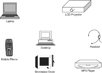
Figure 36.1: Wireless personal area network.
As shown in Figure 36.1, a set of devices can form a personal area network if they are in the radio vicinity of each other (typically 10 meters radius). When a device comes in the vicinity of another device, the Bluetooth protocols facilitate their forming a network. A device can find out what services are offered by the other device and then obtain that service. For example, a laptop can discover the printer automatically and then obtain the print service. Such networks are called ad hoc networks because the network is formed on-the-fly and, once the device gets out of sight, the network is no longer there. Such networks can be formed in the office, at home, in cars and also in public places such as shopping malls and airports.
Bluetooth facilitates forming of an ad hoc network. When two Bluetooth-enabled devices come near to each other, they can automatically form a network and exchange data.
36.2.1 Bluetooth System Specifications
The specifications of the Bluetooth system are as follows:
Frequency of operation: Bluetooth devices operate in the ISM band in the frequency range 2400–2483.5 MHz. This band consists of 79 channels each of 1MHz bandwidth, with a lower guard band of 2MHz and upper guard band of 3.5MHz. When a device transmits its data, it uses frequency hopping: the device transmits each packet in a different channel. The receiving device has to switch to that channel to receive that packet. Though the radio design becomes complex when frequency hopping is used, the advantage is that it provides secure communication. Nominal frequency hop rate is 1600 hops per second.
Bluetooth operates in the ISM band in the frequency band 2400–2483.5 MHz. This band is divided into 79 channels each of 1MHz bandwidth. Frequency hopping at the rate of 1600 hops per second is used to transmit the data.
Modulation: Gaussian frequency shift keying (GFSK) is used as the modulation technique. Binary 1 is represented by a positive frequency deviation and 0 by negative frequency deviation. The radio receiver has to be designed in such a way that the Bit Error Rate (BER) of minimum 0.1% is ensured; that is, the radio should provide a link that ensures that there will not be more than one error for every 1000 bits transmitted.
Operating range: Three classes of devices are defined in Bluetooth specifications:
-
Class 1 devices transmit maximum of 100 mW. The range of such devices is 100 meters.
-
Class 2 devices transmit 10 mW. The range is 50 meters.
-
Class 3 devices transmit 1 mW. The range is 10 meters.
Most of the commercially available devices have a transmitting power of 1 milliwatt and hence a range of 10 meters.
| Note | The normal range of Bluetooth device is 10 meters. However, with increased transmit power, a range of 100 meters can be achieved. |
Services supported: Both data and voice services are supported by Bluetooth devices. For voice communication, synchronous connection-oriented (SCO) links are used that support circuit switching operation. For data communication, asynchronous connectionless (ACL) links are used that use packet switching. The SCO links carry voice. Two types of voice coding are defined in the specifications: PCM based on G.711 standard at 64kbps and continuously variable slope delta (CVSD) modulation technique also at 64 kbps. There is no retransmission of voice packets if they are lost or received in error.
Bluetooth supports both voice and data services. synchronous connection-oriented (SCO) links carry voice. asynchronous connectionless (ACL) links carry data.
For data services, devices exchange data in the form of packets. The receiving device acknowledges the packets or reports that the packet is received in error. If a packet is received with errors, the packet is retransmitted. It is also possible to broadcast packets by one device to all the other devices in the network. However, in broadcast mode there is no acknowledgement or indication that the packet is received with errors. The broadcasting device indicates to the receiving devices how many times a broadcast packet will be transmitted so that at least once every device will receive the packet without errors.
| Note | In Bluetooth, two standard voice coding techniques are used for voice communication. These are 64kbps PCM and 64kbps CVSD (continuously variable slope delta) modulation. |
Data rates: A Bluetooth device can support three synchronous voice channels and one asynchronous data channel. For voice communication, 64kbps data rate is used in both directions. For asynchronous links, two types of channels are defined with different data rates. In asymmetric channel, data rates are 723.2kbps in one direction and 57.6kbps in the other direction. In symmetric channel, data rate is 433.9kbps in both directions.
Network topology: In a PAN, a set of devices form a small network called a piconet. In a piconet, there will be one master and one or more slaves. All the slaves tune to the master. The master decides the hop frequency sequence and all the slaves tune to these frequencies to establish communication links. Any device can be a master or slave. The master/slave terminology is only for the protocols, the device capabilities are not defined by this terminology. It is also possible for a master and slave to switch roles—a slave can become a master. A piconet can have maximum number of seven slaves that can actively communicate with the master. In addition to these active slaves, a piconet can contain many slaves in parked mode. These parked devices are synchronized with the master, but they are not active on the channel. The communication between the master and the slave uses time division duplex (TDD).
The network formed by a set of devices is called a piconet. In a piconet, a device acts as a master and all others are slaves. A piconet can have a maximum of seven active slaves.
Figure 36.2 shows the various topologies of a Bluetooth piconet. In Figure 36.2(a), a piconet is shown with one master and one slave. It is a point-to-point communication mode. In Figure 36.2(b), the piconet consists of a master and a number of slaves. It is a point-to-multipoint communication mode. Figure 36.2(c) shows a scatternet, which is formed by a number of piconets with overlapping coverage areas. In this scatternet, each piconet will have a master and a number of slaves. The master of a piconet can be a slave in another piconet. Each piconet in the scatternet will have its own frequency hopping sequence, and hence there will be no interference between two piconets.
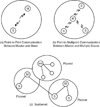
Figure 36.2: Bluetooth piconet (a) Point-to-Print Communication Between Master and Slave (b) Pont-to-Multipoint Communication Between Master and Multiple Slaves (c) Scatternet.
A scatternet is formed by a number of piconets with overlapping coverage areas. Within a scatternet, a master in one piconet can be a slave in another piconet.
Security: To provide security of data over the radio medium, the specifications contain the following features:
-
Each Bluetooth device is given a 48-bit address. This address uniquely identifies the device.
-
When two devices have to communicate with each other, an authentication procedure is used. Every Bluetooth device has a random number generator that generates random numbers that are used for authentication.
-
Data on the channel is encrypted so that only the intended recipients can receive it.
-
The frequency hopping scheme provides built-in security because only those devices that know the hopping sequence can decode the data sent by the master.
| Note | Security is a major issue in all radio systems. Bluetooth provides security through a frequency hopping scheme, encryption of the data, and an authentication procedure. |
Communication between master and slave: The master and slave communicate in the form of packets. Each packet is transmitted in a time slot. Each time slot is of 625 microseconds duration. These slots are numbered from 0 to 227 – 1. The master starts the transmission in even slots by sending a packet addressed to a slave, and the slave sends the packets in odd-numbered slots. A packet generally occupies one time slot but can extend up to five slots. If a packet extends to more than one slot, the hop frequency will be the same for the entire packet. If the master starts the transmission in slot 0 using frequency f1, the slave transmits in slot 1 using frequency f2, the master transmits in slot 2 using frequency f3, and so on.
| Note | Within a piconet, the master always transmits in the even-numbered slots and the slave sends in the odd-numbered slots. The slots are continuously numbered from 0 to 227 – 1. |
States of a Bluetooth device: A Bluetooth device can be in one of two major states: connection state and standby state. In connection state, the device is communicating with another device by exchanging packets. In standby state, the device is not communicating with another device and will be in low-power mode to save battery power, which is the default state. There can be seven substates: page, page scan, inquiry, inquiry scan, master response, slave response, and inquiry response. The state transition diagram is shown in Figure 36.3.
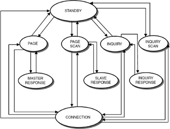
Figure 36.3: State transition diagram.
A device can be in one of the two major states: connection state and standby state. The various substates are page, page scan, inquiry, inquiry scan, master response, slave response, and inquiry response.
To start with, an application program in a Bluetooth device can enter the inquiry state to inquire about other devices in the vicinity. To respond to an inquiry, the devices should periodically enter into inquiry scan state and, when the inquiry is successfully completed, it enters the inquiry response state. When a device wants to connect to another device, it enters the page state. In this state, the device will become the master and page for other devices. The command for this paging has to come from an application program running on this Bluetooth device. When the device pages for the other device, the other device may respond, and the master enters the master response state. Devices should enter the page scan state periodically to check whether other devices are paging for it. When the device receives the page scan packet, it enters the slave response state.
Once paging of devices is completed, the master and the slave establish a connection, and the connection is in active state, during which the packet transmission takes place. The connection can also be put in one of the three modes: hold, sniff, or park mode. In hold mode, the device will stop receiving the data traffic for a specific amount of time so that other devices in the piconet can use the bandwidth. After the expiration of the specific time, the device will start listening to traffic again. In sniff mode, a slave will be given an instruction such as "listen starting with slot number S every T slots for a period of N slots." So, the device need not listen to all the packets, but only as specified through the sniff parameters. The connection can be in park mode, wherein the device listens to a beacon signal from the master only occasionally; it synchronizes with the master but does not do any data transmission.
A typical procedure for setting up a Bluetooth link is as follows:
-
The device sends an inquiry using a special inquiry hopping sequence.
-
Inquiry-scanning devices respond to the inquiry by sending a packet. This packet contains the information needed to connect to it.
-
The inquiring device requests a connection to the device that responded to the inquiry.
-
Paging is used to initiate the connection with the selected device.
-
The selected device that has entered the page scan state responds to the page.
-
If the responding device accesses the connection, it synchronizes with the master's timing and frequency hopping sequence.
Packet format: The packet format is shown in Figure 36.4. The packet consists of access code (68 or 72 bits), header (54 bits), and payload (0 to 2745 bits). Packets can contain only access code (shortened access code with 68 bits only), access code and header, or access code, header, and payload.
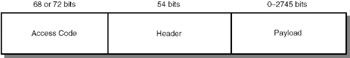
Figure 36.4: Bluetooth packet format.
Access code: All packets in a piconet will have the same access code. Access code is used for synchronization and identification of devices in a piconet. Access code is used for paging and inquiry procedures, and in such cases no header or payload is required because only signaling information is carried.
Access code can be of three types:
-
Channel access code (CAC): Identifies a piconet; all packets in a piconet contain this code.
-
Device access code (DAC): This code is used for paging and response to paging.
-
Inquiry access code (IAC), which is of two types: General IAC is used to discover which Bluetooth devices are in the radio range. Dedicated IAC is common for devices with a common characteristic. Only those devices can be discovered.
Packet header: Packet header is 54 bits long.
-
Three bits for active member address (all zeros for broadcast)
-
Four bits for type code (SCO link or ACL link, how many slots the packet will occupy and such)
-
One bit for flow control (if buffer is full, 0 for stop and 1 to go)
-
One bit for acknowledgement indication (1 indicates that packet is OK, 0 indicates packet error)
-
One bit for sequence number (for each packet, this bit is reversed)
-
Eight bits for header error control for error checking
These total 18 bits. Rate 1/3 FEC is used to make it 54 bits by repeating each bit three times to help in error correction at the receiving end if there are transmission errors.
Note that three bits are allocated for the address of the active device, and so the number of addresses in a piconet to eight. Out of these, one address (all zeros) is for broadcasting the packets in a piconet. So, we are left with seven addresses and hence only seven active devices can be in a piconet.
Bluetooth profiles specify the precise characteristics and protocols to be implemented for specific applications such as file transfer, serial communication, and cordless telephony.
Payload: This field contains the user information, which can be either data or voice.
Bluetooth addressing: Each Bluetooth module (the radio transceiver) is given a 48-bit address containing three fields; LAP (lower address part) with 24 bits, upper address part (UAP) with 8 bits, and non-significant address part with 16 bits. This address is assigned by the manufacturer of the Bluetooth module and consists of company ID and a company-assigned number. This address is unique to every Bluetooth device. In Bluetooth specifications, this address is referred to as BD_ADDR.
Each active member in a piconet will have a 3-bit address. In addition to the maximum of seven active members, many more devices can be in parked mode. The parked members also need to have addresses so that the master can make them active for exchange of packets. A parked member address is either the BD_ADDR of 48 bits or an 8-bit parked member address denoted by PM_ADDR.
Bluetooth profiles: To ensure interoperability between devices manufactured by different vendors, Bluetooth SIG released the Bluetooth profiles, which define the precise characteristics and protocols supported by these devices. The Blueooth profiles are defined for headset, cordless phone, fax machine, LAN access point, serial communication, dial-up networking, file transfer, synchronization of data between two devices, and others.
36.2.2 Bluetooth Protocol Architecture
The complete protocol stack of a Bluetooth system is seen in Figure 36.5.
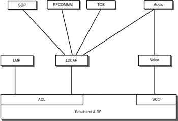
Figure 36.5: Bluetooth protocol architecture.
Baseband and RF
The baseband layer is for establishing the links between devices based on the type of service required—ACL for data services and SCO for voice services. This layer also takes care of addressing and managing the different states of the Bluetooth device. The RF portion provides the radio interface.
Link Manager Protocol
The Link manager protocol (LMP) is used to set up and control links. The three layers RF, link controller and the link manager will be on the Bluetooth module attached to the device. The link manager on one device exchanges messages with the link manager on the other device. These messages, known as LMP messages, are not propagated to higher layers. Link messages have higher priority than data. LMP messages are sent as single slot packets, with a header of 1 byte. The functions of the LMP are as follows:
-
Authentication: When two devices have to communicate with each other, one has to verify the other device. So, one device is called the verifier and the other is called the claimant. The verifier sends a packet containing a random number, which is called a challenge. The claimant calculates the response, which is a function of the challenge, and sends the response along with its Bluetooth address (48-bit address) and secret key. This is known as a challenge-response scheme—you throw a challenge and check whether the other device can correctly respond to that challenge.
-
Encryption: To maintain confidentiality of data over the radio link, the data is encrypted. The master sends a key with which the data is encrypted to all the slaves, through an LMP message.
-
Clock offset request: To synchronize the clocks between the master and the slaves is a must for proper exchange of data. If the clock has to be offset, the LMP exchanges messages to ensure clock synchronization.
-
Timing accuracy information request: To ensure synchronization, the master can ask the slaves for timing accuracy information.
-
LMP version: It needs to be ensured that both devices use the same version of LMP. To achieve this, the version number of the LMP protocol is exchanged.
-
Type of packets supported: Different Bluetooth-enabled devices may support different features, so an LMP features request and response are exchanged between the devices.
-
Switching master/slave role: In a piconet, a device will act as a master and other devices will act as slaves. The master and a slave in a piconet can switch roles using the LMP messages. The master or the slave can initiate the switching operation.
-
Name request: Each device can be given a user-friendly name having a maximum of 248 bits in ASCII format. A device can ask for the name through an LMP message and obtain the response.
-
Detach: Messages exchanged to close a connection.
-
Hold mode: Places an ACL link in hold for a specified time when there is no data to send. This feature is mainly to save power.
-
Park mode: In synchronization with the master but not participating in data exchange.
-
Power control: Asks to transmit less power. This is useful particularly for class 1 devices, which are capable of transmitting 100 mW power.
-
Quality of service (QoS) parameters exchange: In applications that require a good quality transmission link, quality of service parameters can be specified. These parameters include the number of repetitions for broadcast packets, delay, and bandwidth allocation.
-
Request SCO link: Request an SCO link after the ACL link is established.
-
Multislot packet control: Controls the procedure when data is sent in consecutive packets.
-
Link supervision: Monitors link when device goes out of range (through a timeout mechanism).
-
Connection establishment: After paging is successfully completed, establishes the connection.
The Bluetooth device will implement these three layers in a hardware/firmware combination. These three layers ensure establishment of a connection and managing the connection for transfer of voice or data. To ensure that the whole application runs per user requirements, we need lots of other protocols.
The functions of link manager protocol are to set up and control the radio links. Authentication, switching between master and slave roles, and link supervision to monitor the link are done at this layer.
Logical Link Control and Adaptation Protocol (L2CAP)
L2CAP runs above the baseband and carries out the datalink layer functionality. L2CAP layer is only for ACL links. L2CAP data packets can be up to 64 kilobytes long. L2CAP protocol runs on the host such as laptop, cellular phone, or other wireless devices.
L2CAP does not do any checksum calculation. When L2CAP messages are exchanged between two devices, it assumes that an ACL link is already established between two devices. It also assumes that packets are delivered in sequence. Note that L2CAP does not support SCO links for voice communication. L2CAP does not support multicasting.
The functions of L2CAP layer are:
-
Protocol multiplexing: In the protocol stack seen in Figure 36.5, above L2CAP, a number of other protocols can be running. A packet received by L2CAP has to be passed on to the correct higher layer. This is protocol multiplexing.
-
Segmentation and reassembly: Baseband packets are limited in size as we saw in packet format. Large L2CAP packets are segmented into small baseband packets and sent to the baseband. Similarly, the small packets received from the baseband are reassembled and sent to higher layers.
-
Quality of service: Quality of service (QoS) parameters such as delay can be specified, and this layers ensures that the QoS constraints are honored.
The L2CAP layer sends connection request and QoS request messages from the application programs through the higher layers. It receives from the lower layers the responses for these requests. The responses can be connection indication, connection confirmation, connect confirmation negative, connect confirmation pending, disconnection indication (from remote), disconnect confirmation, timeout indication, and quality of service violation indication.
The functions of the L2CAP layer are protocol multiplexing, segmentation and reassembly, and ensuring that the quality of service parameters are honored. This layer is only for ACL links, in other words, for data applications.
Service Discovery Protocol
The service discovery protocol (SDP) provides the Bluetooth environment the capability to create ad hoc networks. This protocol is used for discovering the services offered by a device. SDP offers the following services:
-
A device can search for the service it needs in the piconet.
-
A device can discover a service based on a class of services (for example, if a laptop wants a print service, it can find out the different printers available in the piconet—dot matrix printer, laser printer, etc., and then subsequently select the desired print service).
-
Browsing of services.
-
Discovery of new services when devices enter RF proximity of other devices.
-
Mechanism to find out when a service becomes unavailable when the device goes out of RF range (when there is no RF proximity).
-
The details of services such as classes of services and the attributes of services.
-
It can discover services on another device without consulting the third device.
When a device wants to discover a service, the application software initiates the request (the client), and the SDP client sends SDP request to the server (the device that can provide the required service). SDP client and server exchange SDP messages. Note that the server and client can be any two devices—the server is the device that can provide the service being requested by the client.
The server maintains a list of service records. Each record is identified by a 32-bit number for unique identification. The service record will have a number of attributes. The attributes can be service class ID list (type of service), service ID, protocol description list (protocol used for using the service), provider name, icon URL (an iconic representation of the service), service name, and service description. Each attribute will have two components: attribute ID and attribute value.
The service discovery protocol (SDP) provides the capability to form ad hoc networks in a Bluetooth environment. When two devices come near to each other, using SDP, a device can obtain the list of services offered by the other device and then access the desired service.
For instance, consider a laptop that requires a print service. The laptop is a client looking for a print service in a Bluetooth environment. The procedure for obtaining this service is as follows:
-
Client sends a service search request specifying the print service class ID to the server.
-
Server sends a service search response to the client indicating that two print services are provided.
-
Client sends a service attribute request and a protocol descriptor list to the server, asking for the details of the service.
-
Server sends the response to the client indicating that PostScript print service is provided.
The SDP is the heart of the Bluetooth system because it provides the capability to discover availability of services and the details of the services, along with the necessary information such as protocols to access the service.
RFCOMM
RFCOMM is a transport protocol to emulate serial communication (RS232 serial ports) over L2CAP. Through RFCOMM, two devices can communicate using serial communication protocols over Bluetooth radio. To achieve this, RFCOMM emulates the nine signals of RS232. These signals are
-
102 for signal common
-
103 transmit data (TD)
-
104 received data (RD)
-
105 request to send (RTS)
-
106 clear to send (CTS)
-
107 data set ready (DSR)
-
108 data terminal ready (DTR)
-
109 data carrier detect (DTR)
-
125 ring indicator (RI)
RFCOMM is derived from the GSM specification TS 07.10 for serial emulation. It supports two types of devices. Type 1 devices are communication end points such as computers and printers. Type 2 devices are part of the communication segment such as modems.
RFCOMM is a transport layer protocol to emulate serial communication over L2CAP. A Bluetooth-enabled PC can communicate with a Bluetooth-enabled modem using this protocol.
Telephony Control Protocol Specifications (TCS)
To establish voice communication between two Bluetooth devices, we need the SCO links. SCO links are not handled by L2CAP protocol. However, L2CAP handles the signaling required for establishing voice connections through the Telephony Control Protocol Specification (TCS). Note that it is not abbreviated as TCP: TCP stands for Transmission Control Protocol used in the Internet protocol architecture. TCS defines call control signaling for establishing speech and data calls between Bluetooth devices and mobility management procedures. This protocol is based on the International Telecommunications Union (ITU) standard Q.931, which is the standard for ISDN signaling. TCS messages are exchanged between devices to establish and release calls and to provide supplementary services such as calling line identification (to identify the telephone number of the calling subscriber).
TCS protocol handles call control signaling protocols to establish voice and data calls between Bluetooth devices. This protocol is based on the Q.931 standard, which is used for signaling in Integrated Services Digital Network (ISDN).
Host Control Interface
To Bluetooth-enable a laptop computer, we can connect a small Bluetooth module to the USB port of the laptop and run the protocol stack on the laptop (called the host). The Bluetooth device will have two parts: a module implementing the lower layers (LMP and below) and a software module implementing higher layers (L2CAP and above). The software module runs on the laptop (the host). The host controller interface (HCI) provides a standard interface so that we can buy the hardware module from one vendor and the software module from another vendor. HCI uses three types of packets:
-
Commands, which are sent from the host to the module
-
Events, which are sent from the module to the host
-
Data packets, which are exchanged between the host and the module
The functions of HCI are:
-
Setup and disconnection of the links and configuring the links.
-
Control of baseband features such as timeouts.
-
Retrieving of status information of the module.
-
Invoking the test modes to test the module for local testing of Bluetooth devices.
HCI provides command interface to the baseband controller and link manager as well as access to hardware status and control registers. HCI has to reside in the Bluetooth module connected to the laptop as well as the host. In the Bluetooth module firmware, HCI commands are implemented so that the host can access the baseband commands, link manager commands, hardware status registers, control registers, and event registers. The Bluetooth module is connected to the USB port. The physical bus is the USB port. Three transport layers are defined to get HCI packets from host to the Bluetooth module: (a) USB, (b) RS232 and (c) UART (universal asynchronous receive transmit), a serial interface without error correction.
| Note | HCI software has to reside on both the Bluetooth module attached to a device (such as the PC) and the host (the PC). |
In the host, the bus driver is implemented as software above which the HCI driver software and other higher layer protocol software are implemented. The HCI commands can be categorized as:
-
Link control commands to establish piconets and scatternets
-
Link policy commands to put devices in hold mode/ sniff mode
-
Commands to get information about the local hardware
-
Commands to get the status parameters
-
Commands to test the local Bluetooth module
HCI commands are used to establish piconets and scatternets, to get information about the local Blutooth hardware, and to test the local Bluetooth hardware.
In summary, Bluetooth provides an efficient protocol stack to support voice and data services. The wireless application protocol (WAP) stack can run over the Bluetooth to provide many interesting wireless applications. The reader can refer to the book by Dreamtech Software Team (given in the References section) for details of WAP over Bluetooth.
|
| < Day Day Up > |
|
EAN: 2147483647
Pages: 313