28.3 FRAME FORMAT
|
| < Day Day Up > |
|
28.3 FRAME FORMAT
The Frame Relay frame format is derived from link access protocol balanced (LAPB), which in turn is derived from HDLC. The link layer protocol in Frame Relay is called link access protocol for Frame Relay (LAPF). LAPF frame format is shown in Figure 28.2. The difference between LAPB (or HDLC) and the LAPF is that there is no control field in LAPF. Hence, there is only one type of frame that carries user data, so control information cannot be carried. It is not possible to carry out in-band signaling. Also, flow control and error control cannot be done because there is no sequence number. The Frame Relay header contains the DLCI. Remaining fields have the same significance and functionality as in HDLC.
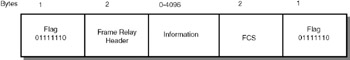
Figure 28.2: LAPF frame format.
The link layer protocol used in Frame Relay is called link access protocol for Frame Relay, abbreviated LAPF. LAPF is derived from HDLC.
Flag: This 8-bit field has a fixed bit pattern 01111110 to identify the beginning of a frame. The same bit pattern appears at the end of the frame.
Frame Relay header: This is a 16-bit field. The details are explained in the next section.
Information: This field contains the user data obtained from the higher layer. The maximum size is 4096 bytes. Though the standard specifies 4096 bytes, 1600 bytes is the ANSI (American National Standards Intstitute) recommendation. Most of the Frame Relay networks are connected to LANs, so 1600 Bytes is recommended because it is compatible with the Ethernet frame size.
FCS: Frame check sequence. Sixteen bits of CRC is used for header error control.
| Note | The LAPF frame consists of the following fields: flag, frame relay header, information, and frame check sequence. The maximum size of the information field is 4096 bytes, as per the standards. However, 1600 bytes is the recommended size to make the frame compatible with the Ethernet frame size. |
28.3.1 Frame Relay Header
The details of the Frame Relay header are seen in Figure 28.3.
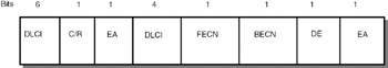
Figure 28.3: Frame Relay header.
DLCI: Data link connection identifier is a 10-bit field split into two portions, one portion containing 6 bits and another portion containing 4 bits.
When a frame is received by a Frame Relay switch, the switch checks whether the data in the frame is correctly received using the frame check sequence field. If there is an error, the frame is discarded.
C/R: Command/response field bit. This bit is used by the FRAD to send a command and receive a response. This command/response is required by some protocols such as SNA (system network architecture) of IBM for signaling and control purposes.
FECN: Forward explicit congestion notification. This bit is used by the switch to inform other switches about congestion.
BECN: Backward explicit congestion notification. This bit is also used by the switch to inform the other switches about congestion.
DE: Discard eligibility indicator. If this bit is set, the frame can be discarded by a switch.
EA: Extension of address. The present Frame Relay header field is restricted to 2 Bytes, with 10 bits for DLCI. If Frame Relay popularity grows and the address capability needs to be extended, the EA bits are required. Using these EA bits, an indication can be sent whether the header is of 3 Bytes or 4 Bytes. This is for future use.
As you can see, the frame format is very simple, and fast switching is achieved. However, because flow control and error control are not supported at the datalink layer, if the frames are received in error at the switch, what needs to be done?
When a frame is received by the switch, it checks the FCS field and verifies whether or not there is an error in the frame. If there is no error, it uses the routing table to forward the frame toward the destination based on the DLCI. If the frame is in error, the frame is discarded. If a frame is received and the DLCI field is wrong (not defined for the link), the frame is discarded. The logic here is simple—if anything is wrong, discard the frame.
If frames are discarded like this, how do we ensure end-to-end reliable data delivery? Frame Relay makes switching faster by transferring flow control and error control to the higher layers. For example, in TCP/IP networks, the TCP layer takes care of flow control and error control, so there is no need to duplicate the work at the link layer. In Frame Relay networks it is the responsibility of higher layers to take care of loss of frames and controlling the flow through acknowledgements by incorporating the necessary protocols.
| Note | There is no flow control and error control in the link layer of Frame Relay, and it is the responsibility of the higher layer to take care of these issues. For instance, if TCP/IP protocol stack is used, the TCP layer will do so. |
|
| < Day Day Up > |
|
EAN: 2147483647
Pages: 313