27.3 ISDN ARCHITECTURE
|
| < Day Day Up > |
|
27.3 ISDN ARCHITECTURE
ISDN system architecture is shown in Figure 27.2. If the subscriber has an ISDN telephone, an ISDN terminal, and an ISDN PBX, they are connected to the network termination-1 (NT1), and NT1 is in turn connected to the ISDN switch. Non-ISDN equipment such as a PSTN telephone, or a normal computer can be connected to the ISDN interfaces through a terminal adapter (TA).
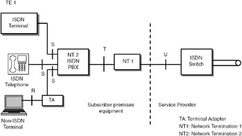
Figure 27.2: ISDN architecture.
In the ISDN architecture, four reference points are defined: R, S, T, and U interfaces. These are conceptual points to describe the interfaces between various equipment.
To ensure that the ISDN-compliant equipment as well as the legacy equipment can be connected through standard interfaces, various interfaces are defined as shown in Figure 27.2. R, S, T, and U interfaces are called the reference points. These reference points are conceptual points to describe the interfaces between various equipment. The advantages of this approach are:
-
Interface standards can be developed at each reference point.
-
Improvements/modifications on one piece of equipment do not have an effect on the other equipment.
-
The subscriber is free to procure equipment from different suppliers.
Terminal equipment: Terminal equipment is of two types—TE1 and TE2. TE1 devices support standard ISDN interfaces such as a digital telephone, integrated voice/data terminals, and digital fax machines. TE2 devices are the present non-ISDN equipment such as PC with RS232 interface computer with an X.25 interface. A terminal adapter (TA) is required to interface the TE2 devices with the ISDN network.
Three types of network terminations are defined in the ISDN architecture: (a) NT1 forms the boundary to the network and is owned by the service provider; (b) NT2 is an intelligent device that can be connected to the ISDN switch and is owned by the subscriber; and (c) NT12 combines the functions of NT1 and NT2 and is owned by the service provider.
Network terminations: Three types of network terminations are defined—NT1, NT2, and NT12. NT1 includes functions associated with physical and electrical terminations of ISDN at user premises. This corresponds to OSI layer 1. NT1 may be controlled by an ISDN service provider and forms a boundary to the network. NT1 also performs line maintenance functions such as loop-back testing and performance monitoring. At NT1, the bit streams from different terminals are multiplexed using synchronous TDM. NT1 can support multiple devices in a multidrop arrangement.
NT2 is an intelligent device that can perform switching functions. It includes functionality up to layer 3 of the OSI model. Equipment such as a digital PBX and a local area network (LAN) are examples of NT2 devices.
NT12 is a single piece of equipment that combines functions of NT1 and NT2. The ISDN service provider owns NT12.
27.3.1 Reference Points
Reference point T (terminal): This reference point corresponds to a minimal ISDN network termination at the subscriber premises. It separates the ISDN service provider's equipment from the user's equipment.
Reference point S (system): This reference point corresponds to the interface of individual ISDN terminals and separates the user terminal equipment from network-related communication functions.
Reference point R (rate): This reference point provides a non-ISDN interface between user equipment that is not ISDN compatible and adapter equipment (such as an RS232 interface to connect an existing PC to ISDN through a terminal adapter).
Reference point U: This reference point provides the interface between the ISDN switch and the network termination-1.
| Note | The interfaces at the reference points are well defined in the standards, so it is possible to integrate equipments supplied by different vendors. |
27.3.2 Narrowband ISDN Channels
In N-ISDN, two types of channels are defined: B channel and D channel. B channel carries user data such as voice/low bit rate video/fax/data. D channel carries signaling data and is also used for low data rate applications such as alarms for the house.
| Note | In narrowband ISDN, two types of channels are defined—B channel and D channel. B channel carries user data, and D channel carries signaling data. |
An ISDN channel can be viewed as a pipe carrying the B channels and D channel. Figure 27.3 shows the ISDN pipes for basic rate interface and primary rate interface.
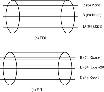
Figure 27.3: ISDN pipe: (a) BRI (b) PRI.
For basic rate interface (BRI), there will be two B channels and one D channel. Each B channel supports 64kbps data rate. The D channel supports 16kbps data rate. Basic ISDN service using two B channels and one D channel at 16kbps is referred to as 2B+D ISDN. The total data rate for 2B + D is 2 × 64 + 16 = 144kbps. With additional overhead of 48kbps, the aggregate data rate will be 192kbps.
| Note | In BRI, there will be two B channels and one D channel. The total data rate is 144kbps. With additional overhead of 48kbps, the aggregate data rate is 192kbps. This interface is referred to as 2B+D ISDN. |
For primary rate interface (PRI), there will be 30 B channels of 64kbps each and one D channel of 64kbps. ISDN service using 30 B channels and one D channel at 64kbps is referred to as 30B+D ISDN. This is the European standard. In North America, the corresponding standard is 23B+D. The aggregate data rate for 30B+D ISDN is 2.048Mbps.
Note that the B and D channels are only logical channels, from the subscriber premises, a single cable will carry the entire data load.
| Note | In primary rate interface (PRI), there will be 30 B channels of 64kbps each and one D channel of 64kbps. The aggregate data rate is 2.048Mbps. This interface is referred to as 30B+D ISDN. |
B Channel
This is the basic user channel to carry PCM voice, data, or fax messages or slow-scan TV data. The different types of connections that can be set up over a B channel are:
-
Circuit-switched calls: These calls are similar to calls of PSTN, but signaling is sent over the D channel.
-
Semipermanent connections: These calls are similar to leased lines of PSTN, and no call establishment procedure is required.
-
Packet-switched calls: The user is connected to a packet-switched network, and data is exchanged using X.25 protocols.
The B channel carries user data such as voice and slow-scan TV. Both circuit-switched calls and packet-switched calls can be setup on the B channel.
D Channel
This channel carries signaling information to control circuit-switched calls. In addition, this channel supports low-speed (up to 100bps) packet-switched data services. Data from energy meters, fire alarms, and such can be sent over the D channel.
D channel carries signaling information. In addition, low speed packet-switched data services can be supported, such as fire alarm data, data from energy meters, and such.
During the initial days of standardization, ISDN was expected to replace analog PSTN through digital technology using BRI and PRI. However, the present installation base of ISDN is very low.
|
| < Day Day Up > |
|
EAN: 2147483647
Pages: 313