Chapter 2: Information Theory
|
| < Day Day Up > |
|
Claude Shannon laid the foundation of information theory in 1948. His paper "A Mathematical Theory of Communication" published in Bell System Technical Journal is the basis for the entire telecommunications developments that have taken place during the last five decades. A good understanding of the concepts proposed by Shannon is a must for every budding telecommunication professional. We study Shannon's contributions to the field of modern communications in this chapter.
2.1 REQUIREMENTS OF A COMMUNICATION SYSTEM
In any communication system, there will be an information source that produces information in some form, and an information sink absorbs the information. The communication medium connects the source and the sink. The purpose of a communication system is to transmit the information from the source to the sink without errors. However, the communication medium always introduces some errors because of noise. The fundamental requirement of a communication system is to transmit the information without errors in spite of the noise.
The requirement of a communication system is to transmit the information from the source to the sink without errors, in spite of the fact that noise is always introduced in the communication medium.
2.1.1 The Communication System
The block diagram of a generic communication system is shown in Figure 2.1. The information source produces symbols (such as English letters, speech, video, etc.) that are sent through the transmission medium by the transmitter. The communication medium introduces noise, and so errors are introduced in the transmitted data. At the receiving end, the receiver decodes the data and gives it to the information sink.
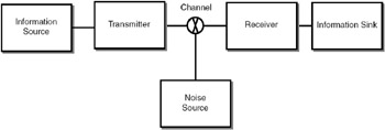
Figure 2.1: Generic communication system
As an example, consider an information source that produces two symbols A and B. The transmitter codes the data into a bit stream. For example, A can be coded as 1 and B as 0. The stream of 1's and 0's is transmitted through the medium. Because of noise, 1 may become 0 or 0 may become 1 at random places, as illustrated below:
| Symbols produced: | A | B | B | A | A | A | B | A | B | A |
| Bit stream produced: | 1 | 0 | 0 | 1 | 1 | 1 | 0 | 1 | 0 | 1 |
| Bit stream received: | 1 | 0 | 0 | 1 | 1 | 1 | 1 | 1 | 0 | 1 |
At the receiver, one bit is received in error. How to ensure that the received data can be made error free? Shannon provides the answer. The communication system given in Figure 2.1 can be expanded, as shown in Figure 2.2.
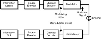
Figure 2.2: Generic communication system as proposed by Shannon.
In a digital communication system, due to the effect of noise, errors are introduced. As a result, 1 may become a 0 and 0 may become a 1.
In this block diagram, the information source produces the symbols that are coded using two types of coding—source encoding and channel encoding—and then modulated and sent over the medium. At the receiving end, the modulated signal is demodulated, and the inverse operations of channel encoding and source encoding (channel decoding and source decoding) are performed. Then the information is presented to the information sink. Each block is explained below.
As proposed by Shannon, the communication system consists of source encoder, channel encoder and modulator at the transmitting end, and demodulator, channel decoder and source decoder at the receiving end.
Information source: The information source produces the symbols. If the information source is, for example, a microphone, the signal is in analog form. If the source is a computer, the signal is in digital form (a set of symbols).
Source encoder: The source encoder converts the signal produced by the information source into a data stream. If the input signal is analog, it can be converted into digital form using an analog-to-digital converter. If the input to the source encoder is a stream of symbols, it can be converted into a stream of 1s and 0s using some type of coding mechanism. For instance, if the source produces the symbols A and B, A can be coded as 1 and B as 0. Shannon's source coding theorem tells us how to do this coding efficiently.
Source encoding is done to reduce the redundancy in the signal. Source coding techniques can be divided into lossless encoding techniques and lossy encoding techniques. In lossy encoding techniques, some information is lost.
In source coding, there are two types of coding—lossless coding and lossy coding. In lossless coding, no information is lost. When we compress our computer files using a compression technique (for instance, WinZip), there is no loss of information. Such coding techniques are called lossless coding techniques. In lossy coding, some information is lost while doing the source coding. As long as the loss is not significant, we can tolerate it. When an image is converted into JPEG format, the coding is lossy coding because some information is lost. Most of the techniques used for voice, image, and video coding are lossy coding techniques.
| Note | The compression utilities we use to compress data files use lossless encoding techniques. JPEG image compression is a lossy technique because some information is lost. |
Channel encoder: If we have to decode the information correctly, even if errors are introduced in the medium, we need to put some additional bits in the source-encoded data so that the additional information can be used to detect and correct the errors. This process of adding bits is done by the channel encoder. Shannon's channel coding theorem tells us how to achieve this.
In channel encoding, redundancy is introduced so that at the receiving end, the redundant bits can be used for error detection or error correction.
In channel encoding, redundancy is introduced so that at the receiving end, the redundant bits can be used for error detection or error correction.
Modulation: Modulation is a process of transforming the signal so that the signal can be transmitted through the medium. We will discuss the details of modulation in a later chapter.
Demodulator: The demodulator performs the inverse operation of the modulator.
Channel decoder: The channel decoder analyzes the received bit stream and detects and corrects the errors, if any, using the additional data introduced by the channel encoder.
Source decoder: The source decoder converts the bit stream into the actual information. If analog-to-digital conversion is done at the source encoder, digital-to-analog conversion is done at the source decoder. If the symbols are coded into 1s and 0s at the source encoder, the bit stream is converted back to the symbols by the source decoder.
Information sink: The information sink absorbs the information.
The block diagram given in Figure 2.2 is the most important diagram for all communication engineers. We will devote separate chapters to each of the blocks in this diagram.
|
| < Day Day Up > |
|
EAN: 2147483647
Pages: 313