Local Area Networks
|
|
A LAN is a small to medium-sized network confined to a specific geographic area such as an office space, floor, or building. The purpose of a LAN is to allow the connection of servers, workstations, printers, and other peripherals so that these resources can be shared among users. A LAN can be connected using a variety of setups or topologies. In a modern LAN, devices are usually connected using twisted-pair cabling. More secure LANs use fiber-optic cabling, which offers benefits such as higher security due to it being harder to tap into in order to monitor network traffic. A newer technology known as wireless Ethernet protocol allows LANs to be connected without any physical wiring. In addition to the cabling used, there are a number of protocols that are responsible for transmitting the data across a network.
| Exam Warning | LANs are broadcast networks. This means that when a device wants to communicate with another device, it sends the data packet across the network so that all other devices can hear it. In a trusted environment, only the device that the packet was intended for will receive it. In a real world environment, you should be aware that data sent across the network can be seen by any listening device and encrypt data across the network accordingly. |
Topologies
There are several physical layouts that a LAN can use to connect computers, printers, cables, and other components. The manner in which all devices on a LAN are connected together is referred to as its topology. The five major physical layouts that most LANs use are the star, ring, bus, tree, and mesh topologies. Each of these topologies transmits and shares data in a slightly different manner.
Star Topology
One of the most common network layouts used today is the star topology. This topology originated when most computer networks revolved around a mainframe computer and it was the central point on the network with all other computers branching off from it. In most networks today, the center of the star topology is usually a central hub or switch. A sample star topology can be seen in Figure 7.4.
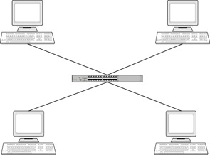
Figure 7.4: The Star Topology: Each Device is Connected to a Central Hub/Switch
Advantages
The major advantage of the star topology is the centralized location of all network connections into a main hub or switch. In this topology, if one computer on the network fails, the other computers on the network are not affected. Because of this advantage, it is possible to add or remove computers on the network without affecting other computers.
In this type of network an administrator can easily remove a computer that may have been compromised by a Trojan Horse or virus. Because of the central management of this type of network, it is very easy to quickly isolate a computer that has become a security risk to your network.
Disadvantages
The star topology's major disadvantage is also its major advantage, which is the centralized location of all network connections into a main hub or switch. If this central hub or switch fails, the entire network can come to a halt very quickly. All client computers will lose their connection to each other and to the servers on the network.
This type of failure, however, can be easily fixed by replacing the central hub or switch that has failed. It is recommended in the star topology to have a backup hub or switch that can quickly take the place of the failed unit. Some high-end switches, such as the Cisco Catalyst 6500 and 7500, can actively monitor activity and instantly let the administrator know if there is a failure or other errors such as excessive network traffic. When considering the purchase of a hub or switch, monitoring and alerting capabilities should be a relatively important consideration.
Common Network Topologies
The star topology is the most common type of network topology used in production networks today. Therefore, it is very important to completely understand how this type of topology works and what the major security vulnerabilities of this topology are.
The star topology usually has a set of hubs and/or switches at the center of the network. All other devices on the network, including servers, printers, and workstations are connected to this central location. The physical security of this area is very important to overall network security. If these switches and hubs were to be vandalized or malfunctioned, it would cause all communication on the network to stop functioning.
One of my first jobs was at a division of a global corporation that operated in my hometown. This division generated between $50,000 and $100,000 of revenue per day but required the data network to be working or all production was halted and no revenue was generated. The internal IT department was aware of the risks associated with losing the central switch, but were unable to convince upper management to purchase a backup. The central switch eventually malfunctioned and production halted on the network for over half a day. So, because the division did not have a spare switch that, at the time cost under $500, it lost around $50,000 in potential revenue.
It is recommended to purchase a service contract, if available, from the respective vendor that will cover switch replacements should one fail. Some vendors, such as Cisco, offer a four-hour turnaround time on some of their high-end switches.
Another common security risk, discussed later in this chapter, is the broadcast mechanism that is associated with this type of topology.
Bus Topology
The bus topology uses a single cable to connect all computers together. The central cable is usually referred to as the backbone or trunk of the network. All computers on the network, including clients and servers, branch off of this central backbone. The data signal is passed down the backbone and all computers on the network can hear the signal, but only the computer that the packet is addressed to receives the signal. At each end of the backbone, there is a terminator that absorbs the signal so that it does not keep bouncing back and forth across this central cable. An example of a bus topology can be seen in Figure 7.5.
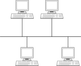
Figure 7.5: Bus Topology: Each Device on the Network Connected to a Single Central Backbone
The bus topology is rarely used in networks today. While it still may be seen in older networks that have not been upgraded, it is commonly being replaced with topologies such as the star topology.
Advantages
The advantages of the bus topology are ease of set up and the fact that if one computer goes down, the network remains up. Since all computers are basically daisy-chained together, an administrator can easily add another computer onto the network.
Disadvantages
There are two major disadvantages to the bus topology. The first disadvantage is the performance issues associated with the network. Since only one computer can transmit data at a time, network performance is severely affected by the number of computers on the network. The second disadvantage is that if there is a cable break, the entire network can go down. It can also be hard to locate this break in a large bus network.
Note that except in the case of older architectures, it is very rare (if it happens at all) that a bus topology will be used today in a new network.
Tree Topology
The tree topology combines both the linear and star topologies. It keeps groups of star topology-based networks connected to each other via a bus topology network. The data packets pass through each small star network, which is controlled from a central hub or switch, and then on each bus segment the data passes through the backbone. An illustration of a tree topology is shown in Figure 7.6. Note that the tree topology can implement meshing at various layers of the network to provide a level of fault tolerance. An example of how you can use the tree topology with meshed switches can be seen in Figure 7.7.
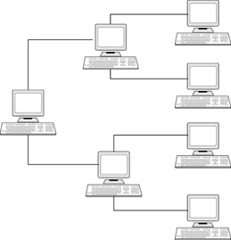
Figure 7.6: The Tree Topology Combines the Star Topology and Bus Topology
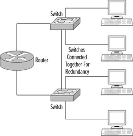
Figure 7.7: The Tree Topology can Utilize Meshing to Increase Fault Tolerance
Advantages
Advantages of the tree topology include many of the same advantages of the star and bus topologies. If one computer goes down, the entire network does not necessarily cease to function. Also, if a section of the network goes down, like a specific segment or branch of the tree topology, the device and cabling for that smaller star topology can be easily located to troubleshoot or replace. Also, the entire network is broken up into smaller segments; the number of data collisions will be reduced on the network.
Disadvantages
A major downfall of the tree topology is that if you have a very large organization with this layout, it can be cumbersome to locate the device causing the problem. Also, if there is a cable break near the top of the network layout, the network will be split into smaller segments and will not be able to communicate with each other.
Token Ring Topology
The token ring topology is composed of all client and server computers connected using a central cable that is looped around. The ring topology has no start and no end, and does not require terminators like the bus topology. All data signals are passed around the token ring in one direction. Each computer on the network looks at the packet and if it is not addressed to it, the computer passes the packet on to the next computer in the loop. Each computer on the network rebroadcasts the signal across the network if the packet is not addressed to it (Figure 7.8). Token ring topology has the most accurate data transmission success rate. Only the device with the token can transmit data.
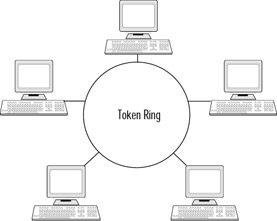
Figure 7.8: A Token Ring Topology
Advantages
The major advantage of the token ring topology is its excellent performance. The token ring topology allows each computer equal access to the network, which allows each computer to communicate when it needs to. The signal is also not subject to degeneration that occurs with other topologies because each computer repeats the signal before passing it to the next computer on the network.
Disadvantages
With the token ring topology, if there is a cable break on the network, the entire network goes down. Also, if one of the computers on the network goes down, the entire network goes down. There are newer ways to implement ring topologies without the risk that the entire network will go down if a single computer on the network breaks.
The token ring topology is at the most risk of network failure out of all the network topologies presented here. The token ring topology is the best choice for a network only if performance of the network is the most important concern and network up time is not. Because of this, the token ring topology is not primarily seen in production networks today.
Mesh Topology
The mesh topology is recognizable because every computer on the network is connected to every other computer. For instance, if there are four computers in a network (A, B, C, and D), then Computer A would have a physical connection going from Computer A to Computer B, a physical connection from Computer A to Computer C, and another connection from Computer A to Computer D (see Figure 7.9). A mesh topology connects each device on the network directly to every other device on the network. This provides redundancy, but is expensive and complex. The mesh topology can be integrated into a tree topology to provide a level of fault tolerance for the network. For example, if the second level of a tree topology contains a switch, the switches can be connected together so that if one of the cables between the first and second levels fail, the entire network will continue to function because the two switches at Level 2 are meshed.
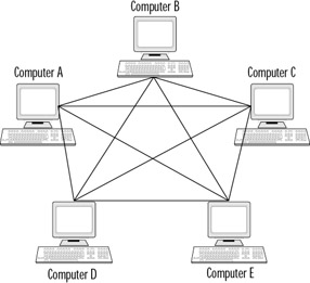
Figure 7.9: A Mesh Topology
Advantages
Redundancy is the biggest advantage that the mesh topology has over the other topologies. The mesh network is extremely fault tolerant. For example, using the A, B, C, and D computers in Figure 7.9, if the connection was severed between Computer A and Computer B, and Computer A and Computer D, A would still be able to communicate with the entire network through the connection between A and C. It is almost impossible for a cable failure to cause a mesh topology to go down. Refer to Figure 7.7 to see how the mesh topology can be combined with the tree topology to provide a simpler method of meshing and still provide significant fault tolerance for the network.
Disadvantages
The mesh topology is very complicated when looking at a network of any size. Because of this complexity, it is very hard to administer. Imagine a LAN containing 500 or 1,000 nodes and each one has a connection to each and every other node in the network.
Another major disadvantage of the mesh topology is cost. Imagine having to buy enough cable to make all network connections possible. This is the main reason that mesh topologies are not more common.
Ethernet
Ethernet is the most widely used technology in networks today. Ethernet is associated with Layers 1 and 2 of the OSI reference model. Ethernet was created when it was decided that there should be a standard used to connect computer networks. In 1980, Digital, Intel, and Xerox released the standard known as Ethernet and later in 1982, they released a newer version knows as Ethernet II. In 1983, the IEEE released the standard knows as Ethernet today as 802.3. The 802.3 standard is very similar to the original Ethernet II standard developed by Digital, Intel, and Xerox. This is now the international standard used for Ethernet today.
Binary to Hex to Decimal Translation
We generally use the base-10 (also known as decimal) numbering system, which uses 10 values (0 through 9) to represent numbers. Computers use the base-2 (also known as binary) numbering system to represent data. The binary numbering system uses two values, 0 and 1, to represent numbers. This is because a computer only recognizes two states: The presence or absence of an electrical charge. Even if a computer is showing decimal numbers, it is merely a translation of the binary numbers inside the machine. A single binary digit (0 or 1) is called a bit. The term octet is used to describe a unit of 8 bits. Most modern computers also have 8 bits in a byte. In the early days of computers, the word byte was also used to describe other quantities of bits. The term nibble is equal to half a byte and is therefore 4 bits, in most cases.
Hexadecimal is base-16 and therefore uses 16 values (0 through 9 and A through F) to represent numbers. The hexadecimal system is useful because a byte (8 bits) of binary data can be represented using just two hexadecimal digits. This makes it easier for humans to read or write large numbers in hexadecimal rather than binary format.
| Note | For additional information regarding the decimal, binary, and hexadecimal conversion, please refer to Chapter 6 "Cryptography". |
Signaling Types
An Ethernet network uses two types of signals to pass data across a network. These two signaling types define what form the physical data bits take when they are passed across the physical medium.
-
Baseband (Digital) Baseband uses digital signaling to transmit data. Signals flow across the medium in the form of pulses of electricity or light. Repeaters are used to allow baseband signals to travel across long distances.
-
Broadband (Analog) Broadband uses analog signaling and a range of frequencies. The signal flows across a cable medium in the form of optical or electromagnetic waves. Signal degradation also occurs with broadband signaling. Repeaters are used to guard against broadband signal degradation. A repeater reconstructs the data packet and passes along the physical medium to its destination.
The two signaling types can both be used at different parts of a data transmission, such as when connecting to the Internet through a dial-up connection. The signal is created on the computer in a digital form, and then goes to the modem. A modem is a digital to analog converter (DAC). This means that the signal begins as baseband (digital) and is then converted to broadband (analog) before traveling across the phone-cabling system.
Note that if the signal is received by an analog system on the other end, such as a modem attached to a remote access server, the maximum connection speed will be 33.6 Kbps. Most ISPs have a digital interface that users commonly dial into, which allows for the maximum transmission speed of 56 Kbps.
Carrier Sense Multiple Access/Collision Detect
Ethernet is based on the Carrier Sense Multiple Access/Collision Detect (CSMA/CD) protocol. CSMA/CD defines the access method used by Ethernet. The term multiple access refers to the fact that many stations attached to the same cable have the opportunity to transmit. Each station is given an equal opportunity to transmit and no individual station has priority over another. Carrier sense describes how an Ethernet station listens to the channel before transmitting. The station ensures that there are no other signals on the channel before it transmits. An Ethernet station also listens while transmitting to ensure that no other station transmits data at the same time. When two stations transmit at the same time a collision occurs. Since Ethernet stations listen to the media while they are transmitting, they are able to identify the presence of others through their collision detection circuitry. If a collision occurs, the transmitting station will wait a random amount of time before retransmitting. This function is known as random backoff.
Traditionally, Ethernet operation has been half-duplex. This means that a station may either transmit or receive data, but it cannot do both at the same time. If more than one station on a segment tries to transmit at the same time, a collision occurs, as per CSMA/CD. When a crossover cable is used to connect two stations, only two stations on the data link need to transmit or receive. The collision detection circuitry is therefore no longer necessary, so machines can be placed in full-duplex mode of operation. This mode allows machines to transmit and receive at the same time, thereby increasing performance.
Token Ring
Token ring is a LAN protocol first developed by IBM in the 1970s and then standardized as IEEE 802.5 in 1985. Token ring supports two bandwidth options, which are 4 Mbps and 16 Mbps. Token ring is unique from Ethernet in that it improves on the common problem of collisions associated with IEEE 802.3. The solution is accomplished by creating a closed ring and using an electronic "token," which is passed around from host to host in the ring. Each host on the ring will look at the token as it is passed around. If a host has to transmit data, it will continue looking at the token until the token indicates that it is that hosts turn to transmit data. After the host transmits data, each other host on the network will look at the token to see if the data is intended for it. The process continues so that only one machine is transmitting data at a time and so that each machine on the network gets an equal opportunity to transmit data.
Only the host that holds the token is allowed to transmit. When a station captures the token, it changes the free token into a busy token frame so that data can be sent. As the token is passed around the ring, stations see this busy token and know not to transmit data onto the network, thus eliminating collisions from occurring.
Frame Detail
A free token consists of three 1-byte fields:
-
Starting Delimiter (SD) Signals the beginning of the token frame.
-
Access Controls (AC) Contains the priority field, reservation field, a token bit, and a monitor bit.
-
Ending Delimiter (ED) Signals the end of the token frame.
A busy token has the following fields in its frame:
-
SD A 1-byte field that signals the beginning of the token frame.
-
AC A 1-byte field that contains the priority field, reservation field, a token bit, and a monitor bit.
-
Frame Control (FC) A 1-byte field that contains two frame-type bits (used to indicate whether this is a MAC or [Logical Link Control] LLC frame), two reserved bits (reserved for future use), and four control bits (used to indicate whether the frame is to be processed by the normal buffer or a high-priority buffer).
-
Destination Address (DA) A 6-byte field that indicates the address of the network adapter for which the frame is intended.
-
Source Address (SA) A 6-byte field that indicates the address of the network adapter that originated the frame.
-
Data This field contains data from upper layers.
-
Frame Check Sequence (FCS) This 4-byte field contains a CRS-32 error check performed on the FC, DA, SA, and the data. This field is not at the frame's end because both ED and frame status (FS) contents may be changed by any station while passing the ring. If FCS were the last field, the checksum would have to be calculated by every ring station again, resulting in lower performance.
-
Ending Delimiter (ED) A 1-byte field that signals the end of the token frame. The ED also contains bits that can indicate a damaged frame and identify the frame that is last in a logical sequence.
-
Frame Status (FS) A 1-byte field that indicates to the transmitting station whether the destination station has copied this frame. This consists of the address-recognized indicator (ARI) bit, the frame copied indicator (FCI) bit, and two bits set to 0. Since this field is not used to calculate the CRC, these four bits are repeated.
Token ring has two different types of frames: LLC frames, which are used for user data, and MAC frames, which are used for adapter-to-adapter communications. MAC frames do not cross bridges, routers, switches, or gateways. Examples of MAC frames include Active Monitor Present, Ring Purge, Standby Monitor Present, Claim Token, and Beacon. LLC frames carry user data and include the LLC header with the upper-layer protocol data. As with Ethernet, the LLC header includes the Destination Service Access Port (DSAP), Source Service Access Port (SSAP), and Control fields.
Token Passing
When a station needs to transmit a frame, it first has to wait for a token to become available. Once it receives the available token, it starts data transmission in a busy frame. As the data moves around the ring, it passes through each station on its way to the destination station. Each station copies the frame to its local buffer and then acts as a repeater and regenerates the frame onto the ring, to be picked up by the next station. When the data arrives at its final destination, it is copied into the token ring card's buffer. The destination station sets the frame-copied indicator and address-recognized indicator bits to 1 and puts the frame back on the ring. The frame continues to be passed around the ring until it returns to its source. The source is responsible for removing the frame and introducing a new free token onto the network. An optional setting can be configured, called early token release, which allows a token to be released by the transmitting station as soon as it has sent its data frame, rather than having to wait for the frame to return from the destination. Early token release allows for multiple frames on the ring, thereby improving performance.
Active Monitor
Token ring is designed with built-in management to constantly monitor and control the ring. This task is performed by a designated station on the ring, known as the active monitor. The active monitor is selected based on an election process known as the claim token process. Once elected, the active monitor is responsible for resolving certain error conditions that might occur on the ring, such as lost tokens and frames or clocking errors. One function of the active monitor is to remove any continuously floating frames from the ring. If a device that has already put a token on the network fails, the frame might continue circulating through the ring forever. The active monitor detects such a frame, removes it from the ring, and generates a new token. The standby monitor is responsible for detecting an active monitor failure and starting the monitor contention process.
Ring purges are generally performed by an active monitor after a recovery operation such as monitor contention has occurred and immediately before the generation of a new token. The active monitor can cause a ring-purge operation by sending out a ring-purge frame, with the purpose of resetting the ring to a known state. Any station receiving the ring-purge frame stops what it is doing immediately, resets its timers, and enters bit-repeat mode. When the active monitor receives its own ring purge frame back, it knows that every station on the ring is now in bit-repeat mode and is waiting for a token.
Beaconing is used to isolate a fault domain so that recovery actions can take place. The beacon process consists of transmitting beacon MAC frames every 20ms without needing a token. The beaconing station uses the clock based on its own internal crystal oscillator and not the clock recovered from its receiver port. When a station receives a beacon MAC frame, it either enters the beacon repeat mode or the beacon transmit mode. A station in the insertion process will terminate its open command with an error and will remove itself from the ring.
Fiber Distributed Data Interface Fiber Distributed Data Interface (FDDI) is a set of specifications used to allow data transmissions over a high-speed medium such as fiber optics. A FDDI network is similar to a token ring network in that it uses token passing to determine what machine on the network can transmit data. An example of an FDDI network can be seen in Figure 7.6. The four specifications that make up FDDI are Physical Medium Dependent (PMD)
-
Physical (PHY)
-
MAC
-
Station Management (SMT)
The PMD level defines the cabling, medium interface connector (MIC), transceivers, photo detectors, and the optical power sources. This specification can be mapped to layer 1 of the OSI model. The cabling defined by this layer includes two rings that transmit data in opposite directions. The first ring is the primary transmission method. The secondary ring exists for redundancy and is rarely used if the first ring is functioning properly. The MIC is the interface between the electrical and optical signals of the architecture. This connector is commonly referred to as a FDDI connector.
The PHY functions between the PMD layer and the MAC layer. At this layer, the electrical signals are processed. Signal encoding and decoding takes place at this layer. This layer can also be mapped to Layer 1 of the OSI model.
The MAC layer is mapped to Layer 2 of the OSI model. This layer defines the frame formats used by FDDI and the access method used by the network. The MAC and PHY layers are built directly into a FDDI chip set.
The SMT layer manages activity on the network. This layer generates frames used for diagnostic purposes, handles connection management on the network, and troubleshoots the network. This is the layer that handles faults with the primary ring and redirects traffic to the secondary ring, if necessary. This layer can also, if necessary, use the second ring to transmit data at double the normal transmission speed.
FDDI Elements
A FDDI network uses several hardware elements to create a functional data transmission system. An example of an FDDI network can be seen in Figure 7.10.
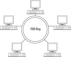
Figure 7.10: A FDDI Ring Uses High-Speed Cabling and Contains Two Rings for Redundancy
-
Stations A station can be either single-attachment station (SAS) or dual-attachment station (DAS). A SAS has only one transceiver that is connected to the primary ring. A SAS cannot be connected to the backbone ring directly. It must be connected using a concentrator, which will be connected to both rings. A DAS has two transceivers that are connected to both the primary and secondary ring.
-
NIC The NIC in a FDDI network contains either one or two transceivers. A FDDI NIC has both a photodetector and a power source.
-
Cable A FDDI network can use either a 62.5-micron single-mode cable or a 125-micron multimode cable. The 62.5 and 125-micron measurements define the diameter of the fiber-optic cable's core. Usually a 125-micron cable is used and one core is used for the primary ring and the other core is used for the secondary ring.
-
Connectors A connector on an FDDI network is called a MIC connector. The MIC provides the connection to the cable while minimizing signal loss. The MIC connectors are made so that you cannot connect the wrong end to the wrong cable. The MIC is a duplex connector so that it can connect to both primary and secondary cables at the same time.
-
Concentrators A concentrator is the wiring center for a node on a FDDI network. Concentrators are connected to the primary and secondary rings. A concentrator can act as a link between an SAS and the secondary ring on the network.
-
Couplers A coupler is used to split a light signal into two or more signals. This allows a signal to be transmitted to multiple nodes on a network. When a light beam is split it is effectively half the power of the original signal.
|
|
EAN: 2147483647
Pages: 135