Section 11.1. Modeling and UML in Context
11.1. Modeling and UML in ContextThroughout the evolution of modeling, practitioners, implementors, academics, and other interested parties have found new and innovative ways to model, and new disciplines to model. It soon became apparent that the generality of the canonical UML was not concise enough for practitioners working full time in a particular language, technology, or platform, such as ANSII C++, Struts, or .Net. Moreover, practitioners in similar disciplines, such as process engineering, with different fundamental structures and constraints found UML interesting but not quite appropriate. They can better benefit from a UML-like language other than UML itself. Figure 11-1 illustrates this situation, where the Meta-Object Facility (MOF), explained more fully later in the chapter, comprises all UML models as well as UML-like models. Figure 11-1. The universe of valid models in UML family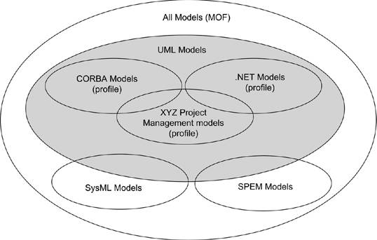 The authors of UML could have specialized UML for common programming languages (such as C++, C#, Java, and Visual Basic) and platforms (such as embedded systems, real-time operating systems (RTOS), EJB, and .NET). This would have created an unworkable modeling language, as each programming language or dialect polluted the specification with conflicting definitions. It would still require an extension mechanism because some "uncommon" language (such as Smalltalk) or new platform/technique or version (like EJB 3.0) would always be missing from the formal specification. On the other hand, the authors could have stretched UML to greater abstraction to embrace uses other than software development, such as business modeling, modeling the process of software development itself, or modeling systems engineering. This would have made everything even more abstract. Because designers work in only one specific domain, abstraction impedes concise expression, moving the models further from their domains. Instead of burdening UML with complexity, or overwhelming it with abstraction, UML's authors factored out everything specific to domains and platforms. They created the profile extension mechanism to address the specific needs of specific application domains. CORBA models, for example, would be concise and precise, but would not influence a .Net model. Although UML cousins, such as the Object Management Group's Software Process Engineering Metamodel (SPEM) and SysML.org's Systems Modeling Language (SysML), borrow much structure from UML, they also discard parts that bring no value to their disciplines. SPEM, best known as the basis for the Rational Unified Process (RUP), describes the process of software development in terms of process roles, work products, and activities. Between a software application and the process of software development, the fundamental structure and relationships between the parts change. Although much is similar in the statechart, class, sequence, package, use case, and activity diagrams, for example, there is no implementation or component diagram, or interface. A profile specializing a few elements works, but it must exclude or constrain many basic concepts. MOF factors out the structure of UML itself for reuse in other disciplines. Using MOF, SPEM and SysML become metamodels at the same level as UML. UML remained close to the disciplines of general software development, and business and data modeling. In other disciplines, a new metamodel can be created from adding, dropping, and reorganizing UML packages to allow for a concise modeling of the discipline. More formally, as seen in Figure 11-2, UML builds on its core infrastructure, MOF. MOF can be used by other modeling languages for other uses. The core UML can be used as is for building models directly, or it can be constrained by one or more profiles. Each level is a level of abstraction. The levels are named M0, M1, M2, and M3, as they become more abstract. M0 is the concrete systemthe code. M1 is the model of the system (of which M0 is just one realization)the model where designers work. M2 is the language used to describe the model, in this case UML and, optionally, the profiles. M3, MOF, is the language used to describe UML and any similar modeling languages. MOF is far beyond the scope of this book. Suffice it to say, though, that MOF provides a formal infrastructure to UML, which explains why stereotypes resemble classes and components, and why tagged values resemble enumerations and attributes. The M1 model, specifying your application, may have profiles associated with it. The architect determines the profiles to use according to the platform, language, and tools available. Deciding the profile effectively freezes the M2 layer. As an application modeler, you model classes, attributes, states, and all the other UML elements. You don't define new stereotypes or tagged values. You assign existing stereotypes. You fill in the values appropriate to the tags. Figure 11-2. Layers of abstraction in UML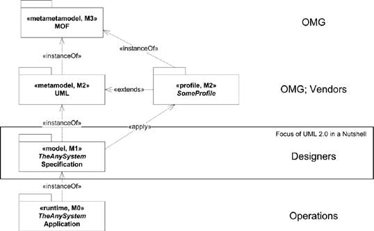 Unless you are also building your own tooling for code generation, reporting, and/or tracking, you will employ the profile(s) as is. As a «singleton», for example, the class needs certain supplementary information. The code generator needs the same questions answered for every «singleton»; no more, no fewer. It makes no sense to have a {multithread-safe=true} tagged value for one «singleton» if the code generator doesn't recognize it. If it does recognize it, every «singleton» should have it. It really depends on the tool. Some teams do build their own tooling. Even then, only the toolsmith works in the M2 layer, and the modelers work in the M1 layer. Changes in the M2 layer must be conservative because one new tagged value in a stereotype can imply revisiting tens or hundreds of elements in the model. Changes in the M2 layer literally change the fundamental meaning of an M1 model. You've been warned. |
EAN: 2147483647
Pages: 132