Section 9.4. Advanced Activity Modeling
9.4. Advanced Activity ModelingUML 2.0 introduces several powerful modeling notations for activity diagrams that allow you to capture complicated behaviors. Much of this new notation is clearly targeted at moving closer to executable models, with things such as executable regions and exception handling. While not all the notations described in this section are used in every model, these constructs are invaluable when applied correctly. 9.4.1. Activity PartitionsThere are times when it is helpful to indicate who (or what) is responsible for a set of actions in an activity diagram. For example, if you are modeling a business process, you can divide an activity diagram by the office or employee responsible for a set of actions. If you are modeling an application, you may want to split an activity diagram based on which tier handles which action. You split an activity diagram using an activity partition. Show an activity partition with two parallel lines, either horizontal or vertical, called swimlanes, with the name of the partition in a box at one end. Place all nodes that execute within the partition between the two lines. Figure 9-25 shows an activity diagram partitioned by business unit. There are times when trying to draw a straight line through your activity diagram may not be possible. You can show that a node is part of a partition by writing the partition name in parentheses above the name of the node. If the activities within Figure 9-25. Activity diagram divided into partitions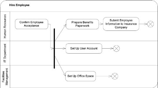 a partition occur outside the scope of your model, you can label a partition with the keyword «external». This is frequently used when performing business modeling using activity diagrams. If the behavior being modeled is handled by someone external to your business process, you can mark the functionality with an external partition. Figure 9-26 shows examples of naming partitions directly on the node and using external partitions. Figure 9-26. Activity diagram with external partitions labeled on the actions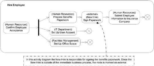 A partition has no effect on the data flow in an activity, however depending on the entity represented by the partition, there are implications on how actions are handled. If a partition represents a UML classifier, any method invocation within that partition must be handled by an instance of that classifier. If the partition represents an instance, the same restrictions apply, except that behaviors must be handled by the specific instance referenced by the partition. For example, if you are modeling a system that has a partition named LoginService, all actions performed within that partition should be handled by an instance of your LoginService. However, if you have a partition that represents an instance of a User class named CurrentUser, all actions in that partition must be handled by the CurrentUser instance. To indicate that a partition represents a class, you use the keyword «class» before the type name. Though the UML doesn't explicitly state it, it is customary to show that a partition represents an instance by underlining the type name. Figure 9-27 shows an example of a partition representing a classifier and a partition representing an instance. Figure 9-27. Activity diagram with partitions representing classes and instances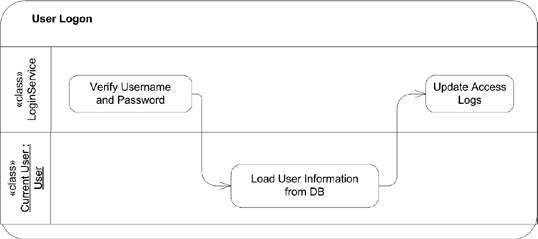 Partitions can also represent attributes with specific values. For example, you can have an activity diagram, which shows that at a certain point in its execution, an attribute has a specific value. You can use a partition to indicate the attribute and value available to actions executing within that partition. Indicate that a partition represents an attribute by placing the keyword «attribute», followed by the name of the attribute in a box above the value boxes. Figure 9-28 is an example of an activity diagram in which the UserRole attribute is specified to indicate what level of access a user needs to perform the given actions. You can combine partitions to show arbitrarily complex constraints on an activity diagram. For example, you can have two partitions that indicate the business department responsible for particular functionality and two partitions indicating the geographic location of the departments. These are called multidimensional partitions and are new to UML 2.0. You can show a multidimensional partition by using both horizontal and vertical intersecting partitions, as shown in Figure 9-29. 9.4.2. Exception HandlingUML 2.0 activity diagrams provide support for modeling exception handling. An exception is an error condition that occurs during the execution of an activity. An exception is said to be thrown by the source of the error and caught when it is handled. You can specify that an action can catch an exception by defining an exception handler. The exception handler defines the type of exception, and a behavior to execute when that particular exception is caught. Figure 9-28. Simple attribute partition example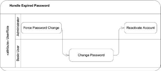 Figure 9-29. Activity diagram with multidimensional partitions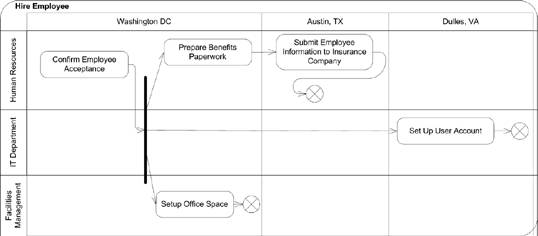 You show an exception handler as a regular node with a small square on its boundary. Draw a lightning-bolt-style edge from the protected node to the small square. Finally, label the edge with the type of the exception caught by this handler. Figure 9-30 shows an example exception handler. If an exception occurs while an action is executing, the execution is abandoned and there is no output from the action. If the action has an exception handler, the handler is executed with the exception information. When the exception handler executes, its output is available to the next action after the protected node, as though the protected node had finished execution. If the action doesn't have an exception handler, the exception propagates to outer nodes until it encounters an exception handler. As the exception leaves a node (an action, structured activity node, or activity) all processing in the node is terminated. It is unspecified what happens if the exception makes it to the top level of a system without being caught; UML 2.0 profiles can define specific behavior to handle this. Figure 9-30. Activity diagram with an exception handler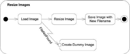 9.4.3. Expansion RegionsYou can show that an action, or set of actions, executes over a collection of input data by placing the actions in an expansion region. For example, if you had an action named Check Out Books that checked each of the provided books out of a library, you can model the checkout book action using an expansion region, with a collection of books as input. You show an expansion region using a dashed rectangle, with rounded corners surrounding the actions that should execute for each piece of input data. Place a row of four input pins on the dashed boundary to represent a collection of data coming into the region. You show a line with an arrow to the row of input pins, and then from the input pins to the input pin of the first internal action. Likewise, you show a row of four output pins on the dashed boundary, with edges coming from the last action's output pin to the row of four output pins on the region. Figure 9-31 shows the Check Out Book expansion region. Figure 9-31. Activity diagram with an expansion region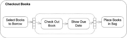 The use of four input pins simply represents a collection of input data; it doesn't specify how much data is actually presented to the expansion region. The region executes for each piece of data in the collection and, assuming there are no errors, offers one piece of output data from each execution. You can use the keywords «parallel», «iterative», or «stream» to indicate if the executions of the expansion region can occur concurrently (parallel), sequentially (iterative), or continuously (stream). Place the keyword in the upper left of the expansion region. Figure 9-32 shows a video encoder that streams the frames through the various stages of encoding as soon as they are available. Figure 9-32. Activity dialog with a streaming region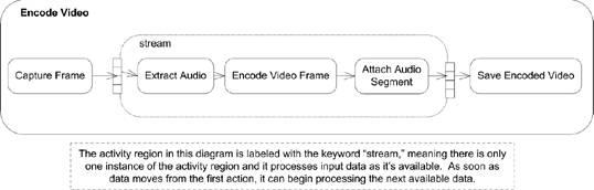 9.4.4. LoopingUML 2.0 defines a construct to model looping in activity diagrams. A loop node has three subregions: setup, body, and test. The test subregion may be evaluated before or after the body subregion. The setup subregion executes only once, when first entering the loop; the test and body sections execute each time through the loop until the test subregion evaluates to false. The specification gives no suggested notation for loop nodes, however you can improvise one using activity regions. Conceptually, a loop node looks like Figure 9-33. Figure 9-33. Conceptual view of a loop node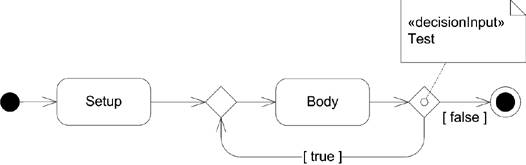 Using activity partitions, you can express this as a single node, as shown in Figure 9-34. Figure 9-34. A sample looping node notation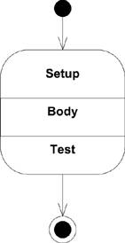 9.4.5. StreamingAn action is said to be streaming if it can produce output while it is processing input. For example, an action representing a compression algorithm can take audio input data from a streamed input and send compressed audio along a streamed output. You indicate that an action is streaming its input and output by placing the keyword stream in braces ({}) near the edges coming in and out of an action. Figure 9-35 shows an example audio encoding that is streaming data. Figure 9-35. Activity diagram with streaming actions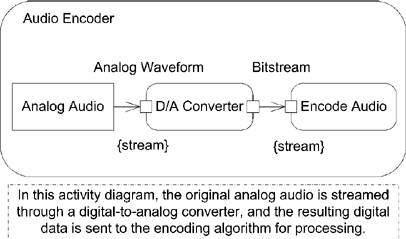 UML provides a shorthand notation for streaming edges, and input and output pins: use a solid arrowhead or rectangle. Figure 9-36 shows the same audio encoder, but is drawn using the streaming shorthand notation. Figure 9-36. Activity diagram with streaming actions using shorthand notation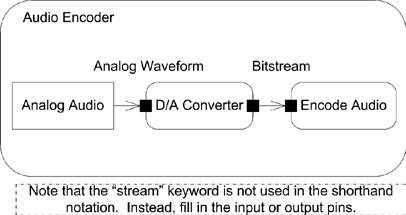 The UML specification expects that vendors will provide base classes for domain-specific activities users can employ to model an application-specific problem. You may also mark a set of actions as streaming using an expansion region. See "Expansion Regions" for more information. 9.4.6. Interruptible Activity RegionsYou can mark that a region of your activity diagram can support termination of the tokens and processing by marking it as an interruptible activity region. For example, you may want to make a potentially long-running database query as interruptible so that the user can terminate things if he doesn't want to wait for the results. You indicate a region is interruptible by surrounding the relevant nodes with a dashed rectangle that has rounded corners. You indicate how the region can be interrupted by drawing a lightning-bolt-style edge leaving the region and connecting to the node that assumes execution. If a token leaves the region over this edge, all other processing and tokens inside the region are terminated. The token leaving the region is unaffected. Typically the source of an interruption is the receipt of a signal from an external entity. You show receipt of a signal as a concave pentagon, with the name of the signal inside. Figure 9-37 shows an example of a long-running database query being interrupted by user input. 9.4.7. Central Buffer NodesUML 2.0 introduced a new type of activity node, called the central buffer node, that provides a place to specify queuing functionality for data passing between object nodes. A central buffer node takes inputs from several object node sources and offers them along several object node outputs. For example, there may be two car-manufacturing plants feeding a car dealer supply line. A central buffer node can be placed between the manufacturing plants and the dealers to specify prioritization of deliveries or sorting of the manufactured cars. You show a central buffer node as a rectangle with the keyword «centralBuffer» at the top and the Figure 9-37. Activity diagram with an interruptible region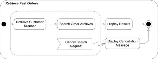 type of object written in the center. Figure 9-38 shows an example central buffer node feeding car dealer supply lines. Figure 9-38. Activity diagram with a central buffer node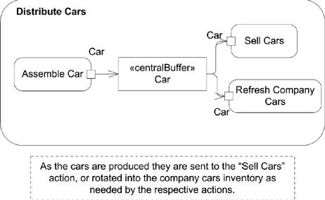 9.4.8. Data Store NodesA data store node is a special type of central buffer node that copies all data that passes through it. For example, you can insert a data store node in your activity diagram to indicate that all interactions are logged to an external database, or that when an article is submitted for review, it is automatically stored in a searchable archive. You show a data store node as a stereotyped version of an object node. Show the node as a rectangle, and place the keyword «datastore» above the name of the node. Figure 9-39 shows a data store node. If the same object passes through a data store node, the specification states that the previous version of the object will be overwritten. Figure 9-39. Activity diagram with a data store node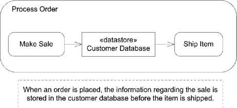 You can show transitions from a data store node that have additional information to select a subset of the data stored in a data store node, similar to a database query. The specification doesn't require any particular syntax and suggests showing the selection criteria in a note labeled with the keyword «selection». Figure 9-40 shows an activity diagram that uses a data store node to send welcome packets to new customers. Figure 9-40. Activity diagram with a data store selection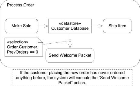 |
EAN: 2147483647
Pages: 132