Section 9.3. Activity Nodes
9.3. Activity NodesUML 2.0 defines several types of activity nodes to model different types of information flow. There are parameter nodes to represent data being passed to an activity, object nodes to represent complex data, and control nodes to direct the flow through an activity diagram. 9.3.1. Parameter NodesYou can represent parameters to an activity or output from an executed activity as parameter nodes. You show a parameter node as a rectangle on the boundary of an activity, with the name or description of the parameter inside the rectangle. Input parameter nodes have edges to the first action, and output parameter nodes have edges coming from the final action to the parameter node. Figure 9-13 shows an example of wood being fed into a paper production activity, and paper being produced at the end. Figure 9-13. Activity diagram with incoming and outgoing parameters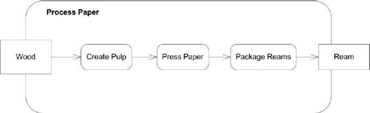 9.3.2. Object NodesTo represent complex data passing through your activity diagram, you can use object nodes. An object node represents an instance of a particular classifier in a certain state. Show an object node as a rectangle, with the name of the node written inside. The name of the node is typically the type of data the node represents. Figure 9-14 is an activity diagram showing a factory producing parts for shipping. Figure 9-14. Object nodes in an activity diagram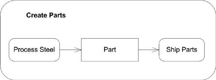 If the type of data the node represents is a signal, draw the node as a concave pentagon. See Figure 9-37 in "Interruptible Activity Regions" for an example of a signal in an activity diagram. 9.3.3. PinsUML defines a special notation for object nodes, called pins, to provide a shorthand notation for input to or output from an action. For example, because the action Ship Parts in Figure 9-14 requires a Part, you can define an input pin on Ship Parts labeled Part. You show a pin using the same rectangle as for object nodes, except the rectangle is small and attached to the side of its action. If it is an input pin, any edges leading into the action should point to the input pin; if it is an output pin, any edges leaving the action should leave from the pin. Figure 9-15 shows the Create Parts diagram rewritten using pins. Figure 9-15. Actions with input and output pins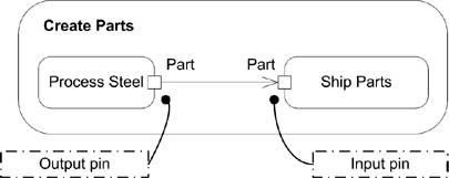 If the output from an action is related to an exception (error condition), you indicate that the pin is an exception pin by inserting a small arrow near the pin. Figure 9-16 shows the Create Parts action with error handling. Figure 9-16. Activity diagram with an exception pin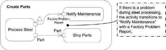 If you don't have edges leading into or out of an action, you can show whether a pin is an input pin or an output pin by placing small arrows inside the pin rectangle. The arrow should point toward the action if you are showing an input pin and away from the action if you are showing an output pin. Figure 9-17 shows an action with input and output pins. If an action takes a constant value as input, you can model the input data using a value pin. A value pin is shown as a normal input pin, except the value of the object is written near the rectangle. Figure 9-18 shows an activity diagram with a value pin. Figure 9-17. Action with input and output pins Figure 9-18. Action with a value pin 9.3.4. Control NodesIn addition to actions, activities may include other nodes to represent decision making, concurrency, or synchronization. These specialized nodes are called control nodes and are described in detail in this section. 9.3.4.1. Initial nodesAn initial node is the starting point for an activity; an initial node can have no incoming edges. You can have multiple initial nodes for a single activity to indicate that the activity starts with multiple flows of execution. You show an initial node as a solid black dot, as shown in Figure 9-4. 9.3.4.2. Decision and merge nodesA decision node is a control node that chooses different output flows based on boolean expressions. Each decision node has one input edge and multiple outgoing edges. When data arrives at the decision node, a single outgoing edge is selected, and the data is sent along that edge. A decision node usually selects an edge by evaluating each outgoing edge's guard condition. A guard condition is a boolean expression that tests some value visible to the activity, typically an attribute of the owning classifier or the data token itself. You show a decision node as a diamond with the flows coming into or out of the sides. You show guard conditions by putting a boolean expression in brackets ([]) near the activity edge. Figure 9-19 is an activity diagram showing a decision made while wrapping presents. Guard conditions aren't guaranteed to be evaluated in any particular order, and a decision node allows only one outgoing edge to be selected. You should take care to design your models so that only one guard condition ever evaluates to true for a given set of data, to prevent race conditions. You can specify functionality that executes whenever data arrives at the decision node. Called decision input behavior, this functionality is allowed to evaluate the data arriving at the node and offers output for the guard conditions to evaluate. The behavior is not allowed to have any side effects when executing, since it can Figure 9-19. Activity diagram with a decision node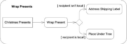 be executed multiple times for the same data input (once for each edge that needs to be tested). You show decision input behavior in a note labeled with the keyword «decisionInput». Figure 9-20 shows an activity diagram that checks to see if a newly authenticated user is the 100th user and should therefore be prompted to take a survey. Figure 9-20. Decision node with an input behavior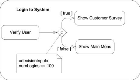 A merge node is effectively the opposite of a decision node; it brings together alternate flows into a single output flow. It doesn't synchronize multiple concurrent flows; see "Fork and join nodes" for concurrency support. A merge node has multiple incoming edges and a single outgoing edge. A merge node simply takes any tokens offered on any of the incoming edges and makes them available on the outgoing edge. You show a merge node using the same diamond you use in a decision node, except with multiple incoming edges and a single outgoing edge. Figure 9-21 shows how a potential new hire's information may be submitted to Human Resources for processing. Figure 9-21. Activity diagram with a merge node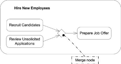 9.3.4.3. Fork and join nodesA fork node splits the current flow through an activity into multiple concurrent flows. It has one incoming edge and several outgoing edges. When data arrives at a fork node, it is duplicated for each outgoing edge. For example, you can use a fork node to indicate that when a new person is hired, actions are initiated by Human Resources, the IT Department, and Facilities Management. All these actions execute concurrently and terminate independently. You show a fork node as a vertical line, with one incoming edge and several outgoing edges. Figure 9-22 is an activity diagram that models hiring a new employee. Figure 9-22. Example activity diagram with a fork node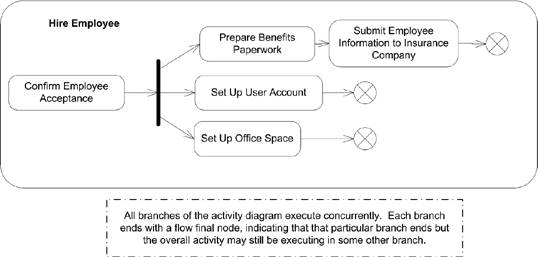 A join node is effectively the opposite of a fork node; it synchronizes multiple flows of an activity back to a single flow of execution. A join node has multiple incoming edges and one outgoing edge. Once all the incoming edges have tokens, the tokens are sent over the outgoing edge. You show a join node as a vertical line, with multiple incoming edges and one outgoing edge. Figure 9-23 is an activity diagram that models serving a meal. Figure 9-23. Example activity diagram with a join node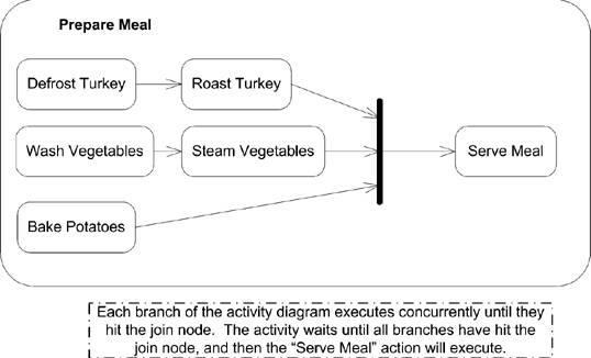 It is worth noting that activity diagrams don't have the advanced time-modeling notations that interaction diagrams have. So, while it's possible to show how to prepare a meal and serve everything at the same time with an activity diagram, you can't capture the time needed to cook each part of the meal. However, you can capture this information with a timing interaction diagram. See Chapter 10 for more information on interaction diagrams. You can specify a boolean condition to indicate under what conditions the join node will emit a token allowing the flow to continue along its single output edge. This expression is called a join specification and can use the names of incoming edges and tokens arriving over those edges in the condition. You write a join specification near the join node inside of braces ({}). Figure 9-24 adds greeting guests to the steps involved in preparing a meal and ensures that you don't serve the meal until all the guests have arrived. 9.3.4.4. Final nodesTwo types of final nodes are used in activity diagrams: activity final and flow final. Activity final nodes terminate the entire activity. Any tokens that arrive at the activity final node are destroyed, and any execution in any other node is terminated, without results. You can have multiple activity final nodes in a single activity diagram, but a token hitting any of them terminates the whole activity. You show an activity final node as a black dot with a circle around it, as shown in Figure 9-4. Flow final nodes terminate a path through an activity diagram, but not the entire activity. Flow final nodes are used when the flow of an activity forks, and one Figure 9-24. Join node with a join specification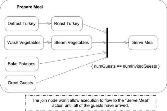 branch of the fork should be stopped but the others may continue. Show a flow final node as a circle with an X in it, as shown in Figure 9-22. |
EAN: 2147483647
Pages: 132