Section 9.1. Activities and Actions
9.1. Activities and ActionsAn activity is a behavior that is factored into one or more actions. An action represents a single step within an activity where data manipulation or processing occurs in a modeled system. "Single step" means you don't break down the action into smaller pieces in the diagram; it doesn't necessarily mean the action is simple or atomic. For example, actions can be:
Translating these into real examples, you can use actions to represent:
When you use an activity diagram to model the behavior of a classifier, the classifier is said to be the context of the activity. The activity can access the attributes and operations of the classifier, any objects linked to it, and any parameters if the activity is associated with a behavior. When used to model business processes, this information is typically called process-relevant data. Activities are intended to be reused within an application, and actions are typically specific and are used only within a particular activity. You show an activity as a rectangle with rounded corners. Specify the name of the activity in the upper left. You can show parameters involved in the activity below the name. Alternatively, you can use parameter nodes, described later in this section. Figure 9-1 shows a simple activity. Figure 9-1. A simple activity with no details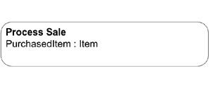 You can show the details for an activity inside of the rectangle, or, to simplify a diagram, leave off the surrounding rectangle altogether. You show actions using the same symbol as an activity: a rectangle with rounded corners; place the name of the action in the rectangle. Figure 9-2 shows some actions inside of an activity. Figure 9-2. Activity with simple details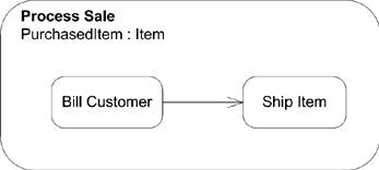 To make activity diagrams more expressive, you can write pseudocode or application-dependent language inside an action. Figure 9-3 shows an example of an action with a domain-specific block of code. Each activity typically starts with an initial node and ends with an activity final node. When an activity reaches an activity final node, the activity is terminated. You show an initial node as a black dot and an activity final node as a solid circle Figure 9-3. An action with pseudocode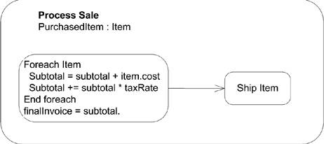 with a ring around it. See "Control Nodes" for more information on initial and final nodes. Figure 9-4 shows an activity with initial and final nodes. Figure 9-4. An activity diagram with initial and final nodes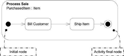 Activities may have pre- and postconditions that apply to the entire activity. You show a precondition by placing the keyword «precondition» at the top center of the activity and then place the constraint immediately after it. You show a post-condition using the keyword «postcondition». Figure 9-5 shows an activity with pre- and postconditions. Figure 9-5. Activity diagram with pre- and postconditions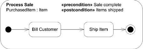 An action may have local pre- and postconditions that should hold true before the action is invoked and after it has completed, respectively. However, the UML specification doesn't dictate how pre- and postconditions map to implementation; violations of the conditions are considered implementation-dependent and don't necessarily mean the action can't execute. You show pre- and postconditions using notes attached to the action. You label the note with the keyword «localPrecondition» or «localPostcondition». Figure 9-6 illustrates this. Figure 9-6. An activity diagram with local pre- and postconditions for actions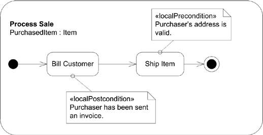 9.1.1. Activity EdgesIn order to show flow through an activity, you link actions together using activity edges. Edges specify how control and data flow from one action to the next. Actions that aren't ordered by edges may execute concurrently; the UML specification leaves it up to the specific implementation of an activity diagram to say whether actions actually execute in parallel or are handled sequentially. You show an activity edge as a line with an arrow pointing to the next action. You can name edges by placing the name near the arrow, though most edges are unnamed. Figure 9-6 (as well as the earlier figures) shows an activity diagram with several activity edges. 9.1.1.1. Control flowsUML offers a specialized activity edge for control-only elements, called a control flow. A control flow explicitly models control passing from one action to the next. In practice, however, few people make the distinction between a generic activity edge and a control flow because the same notation is used for both. 9.1.1.2. Object flowsUML offers a data-only activity edge, called object flows. Object flows add support for multicasting data, token selection, and transformation of tokens. The notation for object flows is the same as that for a generic activity edge. You can use an object flow to select certain tokens to flow from one activity to the next by providing a selection behavior. You indicate a selection behavior by attaching a note to the object flow with the keyword «selection» and the behavior specified. Figure 9-7 shows selecting the top candidates from potential new hires. See "Object Nodes" for details on modeling objects. Figure 9-7. Activity diagram where objects are selected based on a selection behavior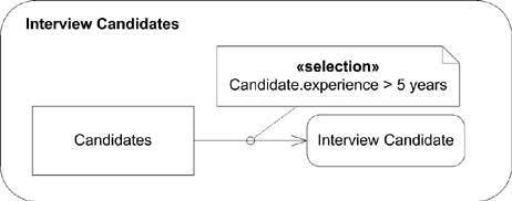 You can assign behaviors to object flows that transform data passed along an edge; however, the behavior can't have any side effects on the original data. You show transformation behaviors using a note attached to the object flow. Label the note with the keyword «TRansformation», and write the behavior under the label. Figure 9-8 shows an example of a transformation behavior that extracts student identification from course registrations to verify that the student's account is fully paid. Object flows allow you to specify sending data to multiple instances of a receiver using multicasting. For example, if you are modeling a bidding process, you can show a Request for Proposal (RFP) being sent to multiple vendors and their responses being received by your activity. You show sending data to multiple receivers by labeling an object flow with the keyword «multicast», and you show data being received from multiple senders by labeling an object flow with the keyword «multireceive». Figure 9-9 shows an activity diagram modeling an RFP process. There are times when an action may accept more than one type of valid input to begin execution. For example, a human resources action named Adjust Salary may require an Employee object and either a New Hire Document or Yearly Performance Review Document, but not both. You can show groups and alternatives for input pins (see "Pins" under "Object Nodes") by using parameter sets. A parameter set groups one or more pins and indicates that they are all that are needed for starting or finishing an action. An action can use input pins only from one parameter set for any given execution, and likewise output on only one output parameter set. You show a parameter set by drawing a rectangle around Figure 9-8. Activity diagram with a transformation behavior to traverse an object and extract the needed information Figure 9-9. Multicast object flows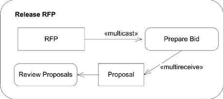 the pins included in the set. Figure 9-10 shows the Adjust Salary action with parameter sets. 9.1.1.3. ConnectorsTo simplify large activity diagrams you can split edges using connectors. Each connector is given a name and is purely a notational tool. You place the name of a connector in a circle and then show the first half of an edge pointing to the connector and the second half coming out of the connector. Figure 9-11 shows two equivalent activity diagrams; one with a connector and one without. Figure 9-10. Action with parameter sets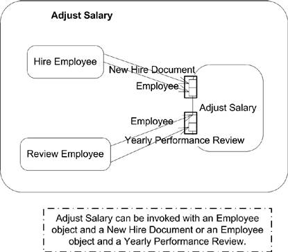 Figure 9-11. Equivalent activity diagrams, one with a connector and one without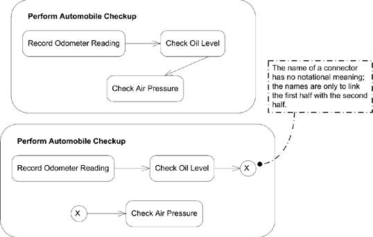 |
EAN: 2147483647
Pages: 132