mVPN Transport
| The previous section discussed the different multicast sources deployment options and how to partition devices to accommodate each choice. In the rest of the chapter, we look at how to transport multicast traffic between virtual devices. We present three main options:
The following sections discuss each of these options in detail GlobalThe simplest architecturejust as with unicast transportis not to virtualize at all. In this scenario, multicast traffic from each virtual network is routed using the global address space. The core and the virtual networks are part of a single multicast domain. Figure 9-10 shows such a network. The access layer uses VLANs. Multicast and unicast traffic to and from the wiring closet is transported first in Ethernet frames and then encapsulated in 802.1q and delivered to the distribution switches. Figure 9-10. Multicast in Global Space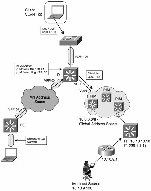 The following scenario is an example of how the global address space runs PIM-SM:
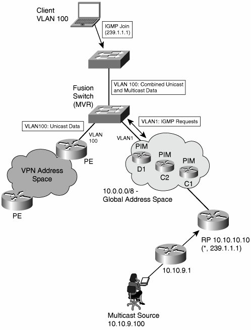
The challenge with the scenario shown in Figure 9-10 is on the distribution switch. Assume that D1 receives a packet with a source-destination pair of (10.10.9.100, 239.1.1.1) on interface Fa1/1. When D1 first runs a RPF check, the unicast forwarding table would show that the route to 10.10.9.100 does indeed use interface Fa1/1, so RPF succeeds. Note If the source is itself in a VRF, the route from the source's first hop to the RP must be leaked into the global table to allow PIM-SM register packets to reach their destination. By global table, we mean a dedicated VRF for multicast traffic. Next, D1 needs to replicate the packet to all members of group 239.1.1.1. The client is in a different virtual network (VLAN100)Figure 9-10 reinforces the separation visually, with oblong shapes on the interfaces that are part of a separate unicast virtual network. On D1, the SVI associated with VLAN100 is mapped to VRF100. So, how can multicast traverse VLANs at Layer 2? The answer is to use Layer 2 VLAN leaking, such as Cisco Multicast VLAN Registration (MVR), to allow select Layer 3 multicast streams to be injected from one VLAN to another. MVR, which was designed for service provider IP/TV environments, allows selective forwarding across VLAN boundaries. When service providers use Layer 2 access solutions for video delivery, multicast is delivered across the network in a dedicated VLAN and must be injected into subscribers' VLANs in the access layer switchit is a Layer 2 equivalent of VRF route leaking. When enabled, MVR listens for IGMP join and leave messages in the unicast VLANs and modifies the multicast forwarding table to include or remove the recipient's interface. In the example in Figure 9-10, MVR runs on D1. When the clients send an IGMP join, MVR updates the global multicast forwarding table with an entry for (*,239.1.1.1) on VLAN100. This allows D1 to send a PIM join request to the RP. When receiving downstream data, MVR allows outgoing packet header information to be written such that (10.10.9.100,239.1.1.1) is encapsulated in VLAN100 and forwarded to the client. Using the global address space to transport multicast is not as easy as it looks. MVR is a Layer 2 solution that may be deployed on a fusion switch to multiplex unicast and multicast Layer 3 data from two different VLANs onto an access layer VLAN. Configuration requires identifying source and receiver ports. In the example, Fa1/1 in VLAN1 would be the source port. Interface VLAN100 would be the one of the receiver port. You can deploy MVR using a dedicated fusion switch as a low-cost method of joining two Layer 3 domains to a last-leg Layer 2 domain. Figure 9-11 shows the fusion-switch deployment model. The fusion functionally can be deployed on the Access switch. Figure 9-11. MVR Fusion Switch The disadvantages of MVR are as follows:
Assuming that something like MVR is available, the advantage of the global address design is that migration is easy. Most enterprise core networks are multicast enabled already and need no configuration changes or software or hardware upgrades. Tunnel OverlayJust as with unicast, you can tunnel multicast data across an IP core. The architecture is a p2p overlay of the sort presented in Chapter 5, "Infrastructure Segmentation Architectures: Theory." In this scenario, the core network does not need to be multicast enabled. All multicast traffic is tunneled across it, most often using multiprotocol generic routing encapsulation (mGRE). Table 9-1 outlines the advantages and disadvantages typical of an overlay network.
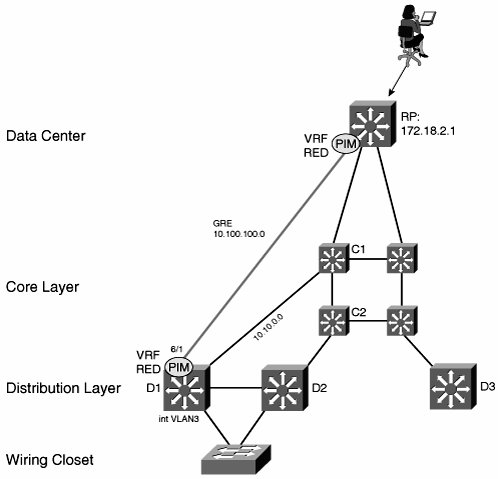
The network shown in Figure 9-12 uses GRE. The GRE endpoints are terminated in VRFs and OSPF (or Enhanced Interior Gateway Routing Protocol [EIGRP]) is used to route VN traffic across the network. GRE packets themselves are routed across the underlying core network using OSPF in a different address space (from the VNs). The global address space does not run multicast routing. Figure 9-12. GRE Tunnel Overlay with Multicast The first step is to build the GRE tunnel infrastructure between each hop and to place them in the appropriate VRFs. Example 9-1 shows the configuration on C1, one of the core switches. Note It might be necessary to create a unique tunnel source-loopback interface for every tunnel. Certain hardware architectures require this to be able to hardware-switch GRE traffic. Example 9-1. GRE Configuration on C1
When the tunnel infrastructure is in place (and tested), add the multicast configuration. We used GRE for simplicity, but you can just as easily replace the configuration in Example 9-1 with mGRE. Multicast works equally well over either. Each VRF in Figure 9-12 has a unicast and multicast component, the latter configured with per-VRF multicast commands, which are applied both globally and per interface. When deploying VRFs over multiple hops, activate per-VRF multicast at every GRE termination hop. You must complete the following steps at every hop to enable multicast for each VRF. First, enable multicast, both globally and in each VRF at every hop (but not on the core interfaces, such as the TenGigabitEthernet ports). Multicast should be running on both the SVI interfaces facing the access and the tunnel interfaces in VRF RED. Example 9-2 shows the commands needed. Example 9-2. Multicast Configuration on D1
Each VN needs a PIM RP. The RP must be inside the VRF, as shown in Example 9-3. The RP device in Figure 9-12 also has a GRE tunnel to C1, which is not shown in the following example. Example 9-3. RP Configuration
The final step is to configure the RP address on all the multicast routers in the RED VRF. One option is to use a static configuration, as follows: ip pim vrf RED rp-address 172.18.2.1 Alternatively, you can use the auto-rp feature, which allows PIM routers to learn RP addresses dynamically. mVPNmVPN was designed to allow service providers to offer multicast service to their enterprise customers. An mVPN network uses the RFC 2547 architecture and shares many of the characteristics of a Multiprotocol Label Switching (MPLS) VPN. One major challenge solved by mVPN is that of core router state requirements. Recall from the discussion of global address space transport earlier in the chapter that every core router has (*,G) state for every VN on the network. In a large network, this just is not realistic. Service providers must carefully manage resource requirements in their core networks. Furthermore, in a VN environment, enterprise customers retain control over multicast group creation. Service providers want to isolate themselves from this. Similarities exist between the problem of managing customer multicast groups and that of managing customer routes. In both cases, a core network needs to be isolated from customer route (or group creation) and, again in both cases, core routers should not store customer route (or group information) in their memory. Note Before looking at mVPN in detail, it is worth pointing out that other proposals exist to address this problem. One is to use VPN-IP PIM, which runs multicast in the core network and leaks customer group information and combines the customers (S,G) and RD to give a unique (RD:S,G) multicast route. This provides separate group spaces to each customer but involves a potentially large resource requirement in the core. Another proposal is to connect PEs using p2mp tunnels. PEs would replicate multicast traffic from CE routers as unicast to other PEs, which would then forward the packets as multicast again. The core network resources are isolated in this scenario, but at the cost of transferring work to the PE CPU. mVPN uses a concept of multicast domains, which is a connected set of mVRFs. Each customer has their own multicast domain, and all customer multicast groups are mapped to their domain across the service provider network. A PE router has as many multicast domains as there are customers connected to it. For any given multicast domain, all the relevant PEs are connected together in an MDT. A PE is part of MDT x if it has a connection to customer xs CE. MDT termination points are called multicast tunnel interfaces (MTIs). More formally, the MTI is the interface that points to the MDT from an mVRF. mVPN requires the core network to run IP multicast to forward mVPN packets between PEs. Note that the requirement is only for native multicastthere is no need for any special features in the core. Each customer appears as a multicast group, so core routers need to store one (*,G) entry only on a per-VPN basis, with an RP for each group (and assuming bi-directional PIM). Again, this is similar to MPLS VPNs, for which P routers need to route only between PEs. mVPN provider (P) routers only know how to multicast between PEs. As stated earlier, all the PEs in a multicast domain are connected in an MDT. There can be more than one MDT per domain:
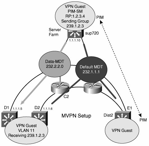
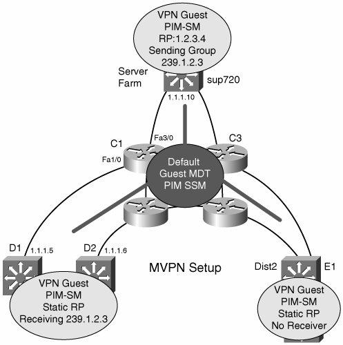
One early criticism with the multicast domain approach lay in the fact that all PEs are part of a default MDT, so they receive multicast traffic for all customer groups, whether they need to or not. To alleviate this, mVPN allows PEs to create data MDTs dynamically that connect only the devices that are part of a particular group. The creation of data MDTs are triggered by data rates in excess of a configured threshold. The same MTI is used to access both the default and data MDTs. Figure 9-13 shows a default and data MDT running on an mVPN network. Figure 9-13. Default and Data MDTs Figure 9-14 shows the two pieces of mVPN that we have not yet covered: CE-PE and PEPE routing adjacencies. A PE has PIM adjacencies with CEs in the same way that a PE is a unicast peer with a CE. PEs also have PIM adjacencies with each other. Depending on the implementation, the mVPN can transport sparse, dense, sparse-dense, bidirectional, and SSM, which means that enterprise networks should not have to make any changes to use an mVPN service. PIM RPs can either be on CE or PE routers (they are part of the customer address space). In either case, you can configure the other PIM routers with static RP information or use auto-rp to perform dynamic RP discovery. PIM control traffic goes over the default MDT, as does all dense-mode (S,G) and shared-tree (*,G) traffic. Figure 9-14. mVPN CE-PE Adjacencies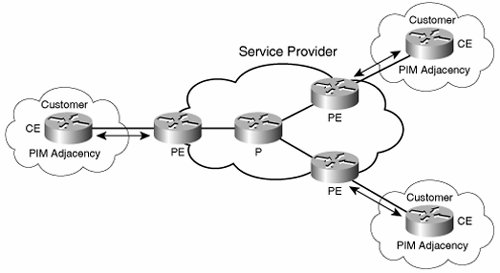 mVPN forwarding follows this scenario:
RPF checking is a critical component of multicast forwarding. RPF on the CE-PE and global network (PE-P and P-P) interfaces is straightforward because unicast routing entries can be used to check whether a packet is received on the right incoming interface. However, PEs also have PIM adjacencies with each other and exchange packets through the MTI. The MTI is never announced in unicast routing updates, so standard RPF checks would fail. To provide a mechanism for RPF to succeed on MTIs, when a packet is received on an MTI, the PE router checks to see whether the source address of the outer packet matches the BGP next-hop of the source address of the inner packet. It also checks whether the source of the outer packet is a PIM peer in the mVRF. RPF succeeds if both these conditions hold. Note that this means that PIM and BGP must use the same address. A PE also uses MP-BGP to announce a new default MDT to its peers. mVPN is another option for deploying multicast over virtualized enterprise networks. Core switches play the role of P, and the mVPN PE function is in the distribution layer. The advantages of mVPN are that it provides a scalable way to transport multicast traffic while meeting the requirements of a VPN, such as private address space support. VPN multicast packets are themselves multicast across default or data MDTs. The core network runs native IP multicast features only. The forwarding path uses GRE, so hardware acceleration is available. Finally, mVPN is transparent to multicast running inside the virtual networksas long as some form of PIM is used. The disadvantages of mVPN include configuration and troubleshootingthere are a lot of protocols to set up and debug. In addition, PEs often need a software upgrade to get the mVPN feature set. Basic mVPN configuration is not as hard as you might imagine. Consider the network in Figure 9-15, which overlays mVPN over the topology introduced in Figure 9-12. Figure 9-15. mVPN Network with Default MDT Assuming that MP-BGP and VRFs are already configured, the first step, shown in Example 9-4, is to enable native multicast routing on all the core switches. All modes of PIM are supported. Example 9-4. mVPN Native Multicast Configuration on C1
Example 9-5 shows the configuration on D1 that creates an mVRF and assigns the 239.1.1.1 group address to the default MDT and 239.2.2.0 to the data MDT. All other PEs that connect to the Guest VRF must use the same group address for the MDTs. Example 9-5. MVRF and MDT Configuration on D1
Example 9-6 gives the MP-BGP portion of D1's configuration. The loopback0 address is used as the MP-BGP source address in Example 9-6 (highlighted in Example 9-6 and 9-5). BGP sessions must exist with all the other mVPN peers. Example 9-6. D1 BGP Configuration
Some final notes on Examples 9-4 through 9-6: The Guest RP address, 1.2.3.4, is part of the Guest VRF address space. VLAN11 is a CE-PE type interface. There must be another PIM router on this interface that peers with D1, with the standard PIM configuration, and none of the MDT statements of Example 9-5. |
EAN: 2147483647
Pages: 128