RFC 2547 VPNs over L2TPv3 Tunnels
| L2TPv3 tunnels provide a transport alternative to GRE. You can use them to create a Layer 3 tunnel overlay similar to that created with GRE tunnels in the previous section. An L2TPv3 mesh supports 2547 over L2TPv3; however, MPLS over L2TPv3 is not an option to date because, as discussed in the previous section, 2547 over L2TPv3 and MPLS over L2TPv3 offer two different types of functionality. To aggregate segmented branches, L2TPv3 must be implemented on the hub router and every branch router having segmentation requirements. The extension of the segmentation into the campus network at the headend can be achieved by h2h VRFs or even by pushing the PE and L2TPv3 tunnel termination functionality all the way into the distribution layer of the campus. In this case, the solution is simple: It is basically a tunnel overlay using VPN labels to mux/demux traffic in and out of the tunnels for the different VPNs, which is similar to the 2547 over GRE solution described in the previous section. Figure 7-15 illustrates the forwarding of packets in an L2TPv3-based 2547 VPN deployment. Figure 7-15. RFC 2547 VPNs over L2TPv3 Packet Flow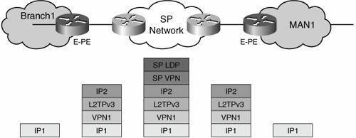 The packet flow is similar to that discussed for 2547 over GRE. There are, however, two differences in the solution:
The use of dynamic multipoint tunnels requires some configuration subtleties. However, these details are the same whether we use mGRE tunnels or L2TPv3 tunnels. The following discussion focuses on L2TPv3 tunnels, but keep in mind that the exact same considerations, and even the same configuration, apply to an mGRE-based approach. The main consideration when configuring dynamic multipoint tunnels is that they need to reside in their own address space. To this effect, you must configure a dedicated VRF for the resolution of next-hop addresses (for example, tunnel endpoints). For this reason, this VRF is known as the resolve in VRF VRF, or RiV VRF. The RiV VRF is straightforward: ip vrf my_riv rd 1:1 The multipoint tunnel interfaces must be included in the RiV VRF. The following table details the commands to create the tunnel for both the mGRE and the L2TPv3 configurations. As you can see, there is only one configuration difference between the two types of encapsulation.
You must configure a route map to ensure that the next hop is resolved within the RiV VRF: route-map SELECT_UPDATES_FOR_L3VPN_OVER_TUNNEL permit 10 set ip next-hop in-vrf my_riv A static route within the VRF ensures that all traffic is sent over the tunnel interface: ip route vrf my_riv 0.0.0.0 0.0.0.0 Tunnel1 You must configure MP-iBGP to peer between the PE and the RRs. To ensure that the next hop for these updates is resolved in the RiV VRF, you now apply the previously created route map to incoming updates: router bgp 100 network 200.0.0.3 neighbor 123.1.1.2 remote-as 100 neighbor 123.1.1.2 update-source Loopback0 ! address-family vpnv4 neighbor 123.1.1.2 activate neighbor 123.1.1.2 route-map SELECT_UPDATES_FOR_L3VPN_OVER_TUNNEL in ! One significant benefit of using a tunnel overlay and extending it end to end (pushing the PE routers all the way to the edges of the IP cloud) is that the entire IP network (including campuses, branches, MANs, and the WAN) can potentially be segmented by a single RFC 2547 VPN domain. This is possible even across autonomous system boundaries in the global table. In other words, the enterprise can have multiple autonomous systems across its IP network. As illustrated in Figure 7-16, regardless of the autonomous system structure of the IP network, an end-to-end mesh of tunnels can be overlaid onto it, and a single autonomous system MP-iBGP process can span the entire network to provide 2547 VPN functionality without any of the inter-autonomous system complexities encountered when using MPLS. Figure 7-16. RFC 2547 VPNs over L2TPv3 Across Autonomous System Boundaries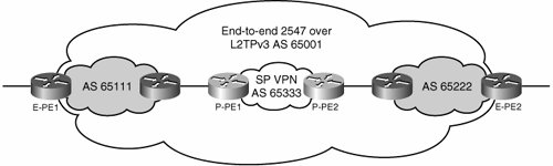 In the figure, the enterprise provides IP connectivity through many autonomous systems. L2TPv3 leverages this connectivity to establish an end-to-end overlay topology. An independent (single Autonomous System) MP-iBGP process rides on top of this logical overlay to provide a single unified RFC 2547 VPN environment that bypasses the inter-autonomous system boundaries. Because no LDP exchange takes place in this solution, the fact that the connections are traversing multiple autonomous systems does not affect the connectivity; hence, the inter-autonomous system label distribution hassles can be avoided. This is true for 2547 over L2TPv3 and 2547 over mGRE deployments. Because no LDP or LSP formation occurs between the PEs, you can actually distribute them across different autonomous systems without breaking the RFC 2547 VPN. However, the same is not true for a service such as MPLS over GRE. In this case, it is not possible to circumvent the inter-autonomous system communication requirements posed by the LDP-based LSP establishment required in an MPLS over X solution. On the other hand, if the campus network or MAN is already segmented with MPLS VPNs and this MPLS deployment is to be preserved, the enterprise is faced with managing an inter-autonomous system exchange point to integrate the MPLS campus/MAN networks with the non-MPLS L2TPv3 WAN network. The most straightforward solution to this problem is to provide CsC services over the L2TPv3-based VPN cloud. The L2TPv3 portion of the network will be the backbone carrier, whereas the MPLS portion of the network will be the customer carrier. Figure 7-17 shows the packet flow for this CsC scenario. Figure 7-17. RFC 2547 VPNs over L2TPv3 as CsC Backbone Carrier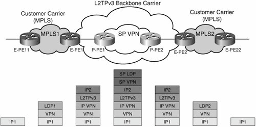 This CsC solution has the same control-plane requirements discussed previously for standard CsC (IPv4 routes and labels for PEs and RRs, VPNv4 routes and labels for enterprise VPN prefixes). In the same way that traditional CsC forms an "extended" LSP by swapping the LDP label in the MPLS packet for a VPN label in the backbone carrier area, this particular CsC implementation swaps labels LDP1 and LDP2 for a VPN label in the L2TPv3 backbone (called "IP VPN" in this example). Note In this case, the enterprise owns and controls both the backbone carrier and the customer carrier portions of the network. Therefore, the limitation on service offerings is no longer present. To configure this CsC solution, you configure the "backbone carrier" portion of the network for 2547 over L2TPv3 as described previously and enable MPLS on the "customer"-facing interfaces of the 2547 over L2TPv3 PEs. The rest of the CsC configuration is identical to that described previously in the "Carrier Supporting Carrier (CsC)" section of this chapter. Inter-autonomous system communication models provide alternative approaches to solving this problem. We introduced the different inter-autonomous system models in the section "MPLS over Layer 2 Circuits." These are fairly complex approaches; therefore, we limit ourselves just to mentioning them rather than providing a detailed description:
Benefits and DrawbacksDeploying RFC 2547 VPNs over IP tunnels does eliminate the need for label switching in the core. However, there are other important benefits to this approach, and some challenges. The benefits of this solution include the following:
The drawbacks include the following:
|
EAN: 2147483647
Pages: 128