Hop-to-Hop VLANs
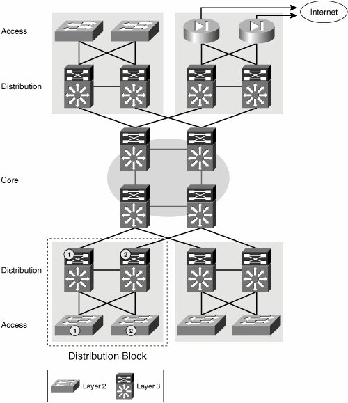
| The first level of segmentation found in any campus network is based on VLANs. Given the scalability limitations of large broadcast domains, the span of VLANs must be kept limited below a certain diameter. The use of VLANs for the virtualization of the network is a viable solution for small networks or portions of a large network. Chapter 2, "Designing Scalable Enterprises," discussed the reasons for not extending VLANs throughout the network and the benefits of having a routed core. However, in a small topology, you can use VLANs to provide segmentation. This is true for portions of the campus network such as the access-distribution module or the LAN portion of a small branch. In these network scenarios, the topology is small enough that the Spanning Tree Protocol (STP) can be used successfully and deterministically to support resilient paths. The limited diameter of the network allows for efficient and reliable spanning-tree reconvergence, limits the reach of a broadcast storm, and makes the spanning-tree domain manageable from a troubleshooting perspective. Deployment recommendations for these domains follow the well-known rules of spanning-tree root bridge positioning and link-cost handling. We do not go into the details of Layer 2 network design, but we do insist that these domains be kept small because they do not provide any failure containment. Figure 6-1 depicts a campus network and highlights the access-distribution block where traffic segmentation can be achieved by means of VLANs. The following are the configuration details necessary to implement VLAN segmentation in the access-distribution block. Note that these do not differ from the well-known common practices for multiple VLAN and STP creation. Figure 6-1. Layer 2 Access-Distribution Block To begin, we need to create the necessary VLANs. To follow standard campus network design best practices, we must avoid spanning VLANs over different access switches. As a result, each user group will have a different VLAN ID on each access switch. The VLANs at the access must be matched at the distribution, which means the number of VLANs at the distribution equals the number of groups times the number of access switches connected to the distribution. The VLANs are the same in both switches in a distribution pair. For Cisco IOS-based switches, Example 6-1 shows the commands needed to create the necessary VLANs for groups Red and Blue on the different access and distribution switches. Note The examples show the commands used on a Catalyst 6500 running Native IOS. Example 6-1. VLAN Segmentation in Access and Distribution
After the VLANs have been created, they must be interconnected throughout the network. You do this by creating 802.1q trunks to carry the VLAN traffic between the switches. Because the access switches are dual homed to the distribution, you must create two trunks to connect each access switch to the distribution pair. Each trunk will carry all VLANs between access and distribution. Example 6-2 illustrates this. Example 6-2. Data Path Virtualization in Access/Distribution
Create a switch virtual interface (SVI) for each VLAN at the distribution switch, as shown in Example 6-3. At this point, you do not assign an IP address to these interfaces. These interfaces are used to map the traffic to the necessary virtual routing and forwarding instances (VRFs) later on. When you have completed the VRF assignment, you assign IP addresses to these. Note In a campus network that is not virtualized, you could have assigned IP addresses to the SVIs at this point. In a virtualized campus network, you must assign the SVIs to the necessary VRFs before you can assign IP addresses to the interfaces. Example 6-3. Virtual Routed Interfaces for VLANs
Finally, assign access ports to the VLANs. Example 6-4 shows the static configuration of access ports. Example 6-4. Assigning Access Ports to the Different VLANs
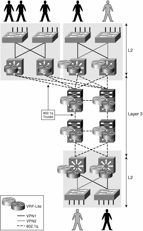
Over a common infrastructure, we have created multiple virtual Layer 2 networks, each of which has its own virtual workgroup space (VLANs), virtual paths (VLANs on a trunk), and dedicated routed virtual interfaces (SVIs). The Layer 2 portion of the network is generally used to access a larger-scale routed network. The following sections discuss some of the mechanisms to virtualize the routed portions of the network. The virtual segments created at Layer 2 and those created at Layer 3 will be associated by common use of the SVIs we have created in this section. Layer 3 Hop to HopThis technique involves the use of VRFs at every hop and the interconnection of the VRFs by means of a Layer 2 circuit such as that identified by an 802.1q tag or a data-link connection identifier (DLCI). Because this technique requires VRFs to be configured and mapped to Layer 2 circuits at every hop, it is generally used to segment the routed portion of a small campus network. This is not a viable solution in an IP-based WAN, where we do not have control over every IP hop. For the IP WAN scenario, multihop techniques provide a viable alternative. Multihop techniques are described in the section "Tunnel Overlay for Layer 3 VPNs." VRF-lite was originally introduced as "Multi-VRF CE" to extend multiple VPNs from a provider edge (PE) onto non-Multiprotocol Label Switching (MPLS) customer edge (CE) devices supporting multiple VRFs. This basically involves a single routed hop and a single link between the PE and CE (that is, no resiliency), as shown in Figure 6-2. Figure 6-2. Multi-VRF CE Original Application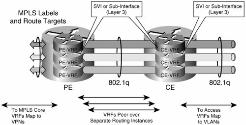 However, you can extend the principle over multiple hops to create virtual campus networks as depicted in Figure 6-3. This also brings to the table the use of multiple links to provide path resiliency. Figure 6-3. Layer 3 Hop-to-Hop Segmented Campus Network We use the network topology in Figure 6-4 to illustrate the configuration required to create Layer 3 hop-to-hop (h2h) virtual campus networks. Figure 6-4. Small Campus Network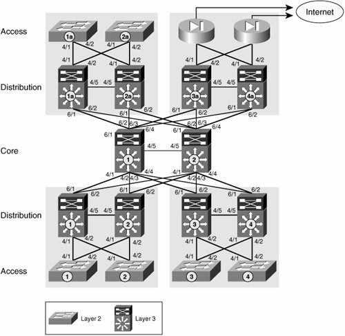 The first step is to create the necessary VRFs. For the h2h Layer 3 solution, it is necessary to create a VRF for each group at every Layer 3 hop. Unique route distinguishers (RDs) must be used for every VRF on a router. Although the RDs across multiple hops do not need to match, it is easier to use a single RD for each group throughout the network. Therefore, all VRFs belonging to the RED group in our example will use the same RD everywhere in the network. This RD differs from the RD used for any other group and is therefore unique. The commands in Example 6-5 create the RED and BLUE VRFs. These commands must be applied at every routed hop in the network. In our example, these are all the distribution and core switches. Example 6-5. Creating VRFs
After the VRFs have been created, the routed interfaces on the distribution switches (SVIs) created in Example 6-3 must be associated with the VRFs. This is achieved via the ip vrf forwarding <name> command, which is used under the interface to be associated with the VRF (see Example 6-6). After the SVIs have been associated with the VRFs, an IP address can be assigned to these. This step must be completed on every distribution switch in the campus network. Example 6-6. Adding Interfaces to VRFs
As you can see, the SVIs for RED1 and RED2 (VLANs 3 and 5) are both associated with the same RED VRF. Thus, two different VLANs are made part of a common routing space by associating them to the same VRF. The VLANs connecting to the distribution and their routed interfaces (SVIs) are to be treated in the same manner as they would be in a nonvirtualized network. For example, first-hop resiliency features such as the Global Load Balancing Protocol (GLBP) or Hot-Standby Redundancy Protocol (HSRP) can be enabled on the SVIs you just included in the VRFs in the same way they would be enabled in a nonvirtualized network. So far, you have created VLANs and associated these to different VRFs at the distribution. The steps followed so far are common to most campus network virtualization approaches; how the VRFs, at the different distribution switches, are interconnected varies depending on the technologies and VPN architectures used. For the specific case of the Layer 3 h2h VPN, we need to associate the VRFs at the distribution with those in the core. The first step is to convert the links in the routed core to dot1q trunks. If consistent interface numbers are used, the template configurations in Example 6-7 would apply to all distribution switches and to all core switches. Note Converting the core links to dot1q trunks is not equivalent to extending Layer 2 domains over the core. These links remain routed; therefore, the VLANs carried on each link differ. Example 6-7. Converting Core Links to Trunks
Because these trunks are meant to be multiple virtual point-to-point (p2p) routed links rather than VLAN extensions, you need to create routed interfaces for the VLANs on each core link. These could be SVIs or subinterfaces. We create SVIs for our example. We need to create one SVI per link for each VRF. In our example, a core switch has nine links and therefore requires the creation of nine SVIs for every VRF supported. Each subinterface will be automatically associated to a VLAN, and therefore a core router in our example will require nine dedicated VLAN IDs per VRF. Furthermore, care must be taken for those VLAN IDs to match the IDs used in any adjacent switches. A numbering convention can prove useful in this scenario. We use four digits, as outlined in Table 6-1.
For instance, VLAN 1214 is used to transport BLUE traffic between Core1 and Distribution 4. VLAN 1124 transports RED traffic over the link between Core2 and Distribution 4. And VLAN 2112 is used to transport RED traffic between Core1 and Core2 and is reused to transport traffic between Distribution 1 and 2, too. Example 6-8 illustrates the creation of the different VLAN IDs required to interconnect the different RED VRFs and the BLUE VRFs. Example 6-8. Creating VLAN IDs for Core Data Path Virtualization
Finally, you must use the ip vrf forwarding name command to associate the routed interfaces (SVIs) with the VRFs, as shown in Example 6-9 Example 6-9. Assigning SVIs to the Appropriate VRFs
At this point, a logical topology overlay of VRFs and virtual routed links has been created. The next step is to enable the control plane (that is, turn on the necessary routing protocols). A separate interior gateway protocol (IGP) process is required for the population of routes in each VN. In our example, we have two VNs: RED and BLUE. When using the Enhanced Interior Gateway Routing Protocol (EIGRP), each process is represented by an address family. The configuration of each address family is identical to that of the traditional nonvirtualized EIGRP. Any EIGRP configuration that needs to be done at the interface level must be done on the routed interfaces associated with the VRFs (subinterfaces or SVIs). The configuration in Example 6-10 illustrates EIGRP address families. Example 6-10. EIGRP Address Families
When using Open Shortest Path First (OSPF), multiple instances of the routing protocol are required. The configuration of each instance is identical to that of the traditional nonvirtualized OSPF. Any OSPF configuration that needs to be done at the interface level must be done on the routed interfaces associated with the VRFs (subinterfaces or SVIs). The configuration in Example 6-11 illustrates how different OSPF instances are associated with different VRFs. Example 6-11. Multiple Instances of OSPF
A proven best practice in IGP design and deployment is that of making the IGP hierarchical. Doing so improves scalability, minimizes convergence times, and prevents events or problems from propagating throughout the entire routed network and causing a global reconvergence of the protocol. In an EIGRP network, you achieve hierarchy by summarizing portions of the network; and in an OSPF network, the concept of areas allows the structuring of the hierarchy. These concepts are discussed in some detail in Chapter 1, but there are books specifically dedicated to routing protocol design. The same best practices for IGP design that have been perfected over the years apply to each of the IGP instances that are created when using a routed h2h virtualization approach. If you use the principles of hierarchy and modularity, all address families will benefit from the scalability and resiliency that characterize a traditional nonvirtualized network. Because each address family is deployed in a hierarchical and symmetrical way, all the mechanisms of resiliency, failover, and scalability will work in the same way as they did for a nonvirtualized network. In addition, the access-distribution block will interact with the core to provide resiliency and failover functionality in the same way as it would for a nonvirtualized enterprise. Therefore, the distribution model in which spanning tree is combined with first-hop redundancy protocols such as HSRP and GLBP continues to operate identically, only that the model is now replicated for each VPN. Similar considerations apply when using a routed access model. |
EAN: 2147483647
Pages: 128