The Bit-Block Transfer
As I mentioned earlier, you can think of the entire video display as one big bitmap. The pixels you see on the screen are represented by bits stored in memory on the video display adapter board. Any rectangular area of the video display is also a bitmap, the size of which is the number of rows and columns it contains.
Let's begin our journey into the world of bitmaps by copying an image from one area of the video display to another. This is a job for the powerful BitBlt function.
Bitblt (pronounced "bit blit") stands for "bit-block transfer." The BLT originated as an assembly language instruction that did memory block transfers on the DEC PDP-10. The term "bitblt" was first used in graphics in connection with the SmallTalk system designed at the Xerox Palo Alto Research Center (PARC). In SmallTalk, all graphics output operations are based around the bitblt. Among programmers, "blt" is sometimes used as a verb, as in "Then I wrote some code to blt the happy face to the screen and play a wave file."
The BitBlt function is a pixel mover, or (more vividly) a raster blaster. As you'll see, the term "transfer" doesn't entirely do justice to the BitBlt function. The function actually performs a bitwise operation on pixels and can result in some interesting effects.
A Simple BitBlt
The BITBLT program shown in Figure 14-1 uses the BitBlt function to copy the program's system menu icon (located in the upper left corner of the program's window) to its client area.
Figure 14-1. The BITBLT program.
BITBLT.C /*--------------------------------------- BITBLT.C -- BitBlt Demonstration (c) Charles Petzold, 1998 ---------------------------------------*/ #include <windows.h> LRESULT CALLBACK WndProc (HWND, UINT, WPARAM, LPARAM) ; int WINAPI WinMain (HINSTANCE hInstance, HINSTANCE hPrevInstance, PSTR szCmdLine, int iCmdShow) { static TCHAR szAppName [] = TEXT ("BitBlt") ; HWND hwnd ; MSG msg ; WNDCLASS wndclass ; wndclass.style = CS_HREDRAW | CS_VREDRAW ; wndclass.lpfnWndProc = WndProc ; wndclass.cbClsExtra = 0 ; wndclass.cbWndExtra = 0 ; wndclass.hInstance = hInstance ; wndclass.hIcon = LoadIcon (NULL, IDI_INFORMATION) ; wndclass.hCursor = LoadCursor (NULL, IDC_ARROW) ; wndclass.hbrBackground = (HBRUSH) GetStockObject (WHITE_BRUSH) ; wndclass.lpszMenuName = NULL ; wndclass.lpszClassName = szAppName ; if (!RegisterClass (&wndclass)) { MessageBox (NULL, TEXT ("This program requires Windows NT!"), szAppName, MB_ICONERROR) ; return 0 ; } hwnd = CreateWindow (szAppName, TEXT ("BitBlt Demo"), WS_OVERLAPPEDWINDOW, CW_USEDEFAULT, CW_USEDEFAULT, CW_USEDEFAULT, CW_USEDEFAULT, NULL, NULL, hInstance, NULL) ; ShowWindow (hwnd, iCmdShow) ; UpdateWindow (hwnd) ; while (GetMessage (&msg, NULL, 0, 0)) { TranslateMessage (&msg) ; DispatchMessage (&msg) ; } return msg.wParam ; } LRESULT CALLBACK WndProc (HWND hwnd, UINT message, WPARAM wParam, LPARAM lParam) { static int cxClient, cyClient, cxSource, cySource ; HDC hdcClient, hdcWindow ; int x, y ; PAINTSTRUCT ps ; switch (message) { case WM_CREATE: cxSource = GetSystemMetrics (SM_CXSIZEFRAME) + GetSystemMetrics (SM_CXSIZE) ; cySource = GetSystemMetrics (SM_CYSIZEFRAME) + GetSystemMetrics (SM_CYCAPTION) ; return 0 ; case WM_SIZE: cxClient = LOWORD (lParam) ; cyClient = HIWORD (lParam) ; return 0 ; case WM_PAINT: hdcClient = BeginPaint (hwnd, &ps) ; hdcWindow = GetWindowDC (hwnd) ; for (y = 0 ; y < cyClient ; y += cySource) for (x = 0 ; x < cxClient ; x += cxSource) { BitBlt (hdcClient, x, y, cxSource, cySource, hdcWindow, 0, 0, SRCCOPY) ; } ReleaseDC (hwnd, hdcWindow) ; EndPaint (hwnd, &ps) ; return 0 ; case WM_DESTROY: PostQuitMessage (0) ; return 0 ; } return DefWindowProc (hwnd, message, wParam, lParam) ; } |
But why stop at one BitBlt? In fact, BITBLT fills its client area with multiple copies of the system menu icon (which in this case is the IDI_INFORMATION icon commonly used in message boxes), as shown in Figure 14-2.
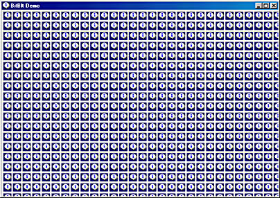
Figure 14-2. The BITBLT display.
The BitBlt function transfers pixels from a rectangular area in one device context, called the source, to a rectangular area of the same size in another device context, called the destination. The function has the following syntax:
BitBlt (hdcDst, xDst, yDst, cx, cy, hdcSrc, xSrc, ySrc, dwROP) ;
The source and destination device contexts can be the same.
In the BITBLT program, the destination device context is the window's client area; the device context handle is obtained from the BeginPaint function. The source device context is the application's whole window; this device context handle is obtained from GetWindowDC. Obviously, these two device contexts refer to the same physical device (the video display). However, the coordinate origins of these two device contexts are different.
The xSrc and ySrc arguments indicate the coordinate position of the upper left corner of the source image. In BITBLT, these two arguments are set to 0, indicating that the image begins in the upper left corner of the source device context (which is the whole window). The cx and cy arguments are the width and height of the image. BITBLT calculates these values from information obtained from the GetSytemMetrics function.
The xDst and yDst arguments indicate the coordinate position of the upper left corner where the image is to be copied. In BITBLT, these two arguments are set to various values to copy the image multiple times. For the first BitBlt call, these two arguments are set to 0 to copy the image to the upper left corner of the client area.
The last argument to BitBlt is called the raster operation. I'll discuss this value shortly.
Notice that BitBlt is transferring pixels from the actual video display memory and not some other image of the system menu icon. If you move the BITBLT window so that part of the system menu icon is off the screen, and you then adjust the size of the BITBLT window to force it to repaint itself, you'll find only part of the system menu icon drawn within BITBLT's client area. The BitBlt function no longer has access to the entire image.
In the BitBlt function, the source and destination device contexts can be the same. You can rewrite BITBLT so that WM_PAINT processing does the following:
BitBlt (hdcClient, 0, 0, cxSource, cySource, hdcWindow, 0, 0, SRCCOPY) ; for (y = 0 ; y < cyClient ; y += cySource) for (x = 0 ; x < cxClient ; x += cxSource) { if (x > 0 || y > 0) BitBlt (hdcClient, x, y, cxSource, cySource, hdcClient, 0, 0, SRCCOPY) ; } This will usually create the same effect as the BITBLT shown above, except if the upper left corner of the client area is obscured in some way.
The most important restriction in BitBlt is that the two device contexts must be "compatible." What this means is that either one or the other must be monochrome, or they both must have the same number of bits per pixel. In short, you can't get a hard copy of something on the screen by blting it to the printer device context.
Stretching the Bitmap
In the BitBlt function, the destination image is the same size as the source image because the function has only two arguments to indicate the width and height. If you want to stretch or compress the size of the image as you copy it, you can use the StretchBlt function. StretchBlt has the following syntax:
StretchBlt (hdcDst, xDst, yDst, cxDst, cyDst, hdcSrc, xSrc, ySrc, cxSrc, cySrc, dwROP) ;
This function adds two arguments. The function now includes separate widths and heights of the destination and source. The StretchBlt function is demonstrated by the STRETCH program, shown in Figure 14-3.
Figure 14-3. The STRETCH program.
STRETCH.C/*---------------------------------------- STRETCH.C -- StretchBlt Demonstration (c) Charles Petzold, 1998 ----------------------------------------*/ #include <windows.h> LRESULT CALLBACK WndProc (HWND, UINT, WPARAM, LPARAM) ; int WINAPI WinMain (HINSTANCE hInstance, HINSTANCE hPrevInstance, PSTR szCmdLine, int iCmdShow) { static TCHAR szAppName [] = TEXT ("Stretch") ; HWND hwnd ; MSG msg ; WNDCLASS wndclass ; wndclass.style = CS_HREDRAW | CS_VREDRAW ; wndclass.lpfnWndProc = WndProc ; wndclass.cbClsExtra = 0 ; wndclass.cbWndExtra = 0 ; wndclass.hInstance = hInstance ; wndclass.hIcon = LoadIcon (NULL, IDI_INFORMATION) ; wndclass.hCursor = LoadCursor (NULL, IDC_ARROW) ; wndclass.hbrBackground = (HBRUSH) GetStockObject (WHITE_BRUSH) ; wndclass.lpszMenuName = NULL ; wndclass.lpszClassName = szAppName ; if (!RegisterClass (&wndclass)) { MessageBox (NULL, TEXT ("This program requires Windows NT!"), szAppName, MB_ICONERROR) ; return 0 ; } hwnd = CreateWindow (szAppName, TEXT ("StretchBlt Demo"), WS_OVERLAPPEDWINDOW, CW_USEDEFAULT, CW_USEDEFAULT, CW_USEDEFAULT, CW_USEDEFAULT, NULL, NULL, hInstance, NULL) ; ShowWindow (hwnd, iCmdShow) ; UpdateWindow (hwnd) ; while (GetMessage (&msg, NULL, 0, 0)) { TranslateMessage (&msg) ; DispatchMessage (&msg) ; } return msg.wParam ; } LRESULT CALLBACK WndProc (HWND hwnd, UINT message, WPARAM wParam, LPARAM lParam) { static int cxClient, cyClient, cxSource, cySource ; HDC hdcClient, hdcWindow ; PAINTSTRUCT ps ; switch (message) { case WM_CREATE: cxSource = GetSystemMetrics (SM_CXSIZEFRAME) + GetSystemMetrics (SM_CXSIZE) ; cySource = GetSystemMetrics (SM_CYSIZEFRAME) + GetSystemMetrics (SM_CYCAPTION) ; return 0 ; case WM_SIZE: cxClient = LOWORD (lParam) ; cyClient = HIWORD (lParam) ; return 0 ; case WM_PAINT: hdcClient = BeginPaint (hwnd, &ps) ; hdcWindow = GetWindowDC (hwnd) ; StretchBlt (hdcClient, 0, 0, cxClient, cyClient, hdcWindow, 0, 0, cxSource, cySource, MERGECOPY) ; ReleaseDC (hwnd, hdcWindow) ; EndPaint (hwnd, &ps) ; return 0 ; case WM_DESTROY: PostQuitMessage (0) ; return 0 ; } return DefWindowProc (hwnd, message, wParam, lParam) ; } |
This program has only one call to the StretchBlt function but uses it to fill the entire client area with its system menu icon, as shown in Figure 14-4.
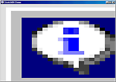
Figure 14-4. The STRETCH display.
All the coordinates and sizes in the BitBlt and StretchBlt function are based on logical units. But what happens when you have two different device contexts in the BitBlt function that refer to the same physical device but have different mapping modes? If this is so, a call to BitBlt might seem ambiguous: the cx and cy arguments are in logical units, and they apply to both the rectangle in the source device context and the rectangle in the destination device context. All coordinates and sizes must be converted to device coordinates before the actual bit transfer. Because the cx and cy values are used for both the source and destination device contexts, the values must be converted to device units (pixels) separately for each device context.
When the source and destination device contexts are the same, or when both device contexts use the MM_TEXT mapping mode, then the size of this rectangle in device units will be the same in both device contexts. Windows can then do a simple pixel-to-pixel transfer. However, when the size of the rectangle in device units is different in the two device contexts, Windows turns the job over to the more versatile StretchBlt function.
StretchBlt also allows you to flip an image vertically or horizontally. If the signs of cxSrc and cxDst (when converted to device units) are different, StretchBlt creates a mirror image: left becomes right, and right becomes left. You can check this in the STRETCH program by changing the xDst argument to cxClient and the cxDst argument to -cxClient. If cySrc and cyDst are different, StretchBlt turns the image upside down. You can check this in the STRETCH program by changing the yDst argument to cyClient and the cyDst argument to -cyClient.
The StretchBlt Mode
StretchBlt can exhibit some problems related to the inherent difficulties of scaling bitmaps. When expanding a bitmap, StretchBlt must duplicate rows or columns of pixels. If the expansion is not an integral multiple, the process can result in some distortion of the image.If the destination rectangle is smaller than the source rectangle, StretchBlt must shrink an image by combining two or more rows or columns of pixels into a single row or column. It does this in one of four ways, depending on the stretching mode attribute in the device context. You use the SetStretchBltMode function to change this attribute:
SetStretchBltMode (hdc, iMode) ;
The value of iMode can be one of the following:
- BLACKONWHITE or STRETCH_ANDSCANS (default)If two or more pixels have to be combined into one pixel, StretchBlt performs a logical AND operation on the pixels. The resulting pixel is white only if all the original pixels are white, which in practice means that black pixels predominate over white pixels. This is good for monochrome bitmaps where the image is primarily black against a white background.
- WHITEONBLACK or STRETCH_ORSCANS If two or more pixels have to be combined into one pixel, StretchBlt performs a logical OR operation. The resulting pixel is black only if all the original pixels are black, which means that white pixels predominate. This is good for monochrome bitmaps where the image is primarily white against a black background.
- COLORONCOLOR or STRETCH_DELETESCANS StretchBlt simply eliminates rows or columns of pixels without doing any logical combination. This is often the best approach for color bitmaps.
- HALFTONE or STRETCH_HALFTONE Windows calculates an average destination color based on the source colors being combined. This is used in conjunction with a halftone palette and is demonstrated in Chapter 16.
Windows also includes a GetStretchBltMode function to obtain the current stretching mode.
The Raster Operations
The BITBLT and STRETCH programs simply copy the source bitmap to the destination, perhaps stretching it in the process. This is the result of specifying SRCCOPY as the last argument to the BitBlt and StretchBlt functions. SRCCOPY is only 1 of 256 raster operations you can use in these functions. Let's experiment with a few others in the STRETCH program and then investigate the raster operations more methodically.
Try replacing SRCCOPY with NOTSRCCOPY. As the name suggests, this raster operation inverts the colors of the bitmaps as it is copied. On the client window, all the colors will be reversed. Black becomes white, white becomes black, and blue becomes yellow. Now try SRCINVERT. You'll get the same effect. Try BLACKNESS. As the name suggests, the entire client area is painted black. WHITENESS makes it white.
Now try this: replace the StretchBlt call with the following three statements:
SelectObject (hdcClient, CreateHatchBrush (HS_DIAGCROSS, RGB (0, 0, 0))); StretchBlt (hdcClient, 0, 0, cxClient, cyClient, hdcWindow, 0, 0, cxSource, cySource, MERGECOPY) ; DeleteObject (hdcClient, GetStockObject (WHITE_BRUSH)) ;
This time you'll see a hatch brush seemingly superimposed over the image. Just what is going on here?
As I mentioned earlier, the BitBlt and StretchBlt functions are not simply bit-block transfers. The functions actually perform a bitwise operation between the following three images:
- Source The source bitmap, stretched or compressed (if necessary) to be the same size as the destination rectangle.
- Destination The destination rectangle before the BitBlt or StretchBlt call.
- Pattern The current brush selected in the destination device context, repeated horizontally and vertically to be the same size as the destination rectangle.
The result is copied to the destination rectangle.
The raster operations are conceptually similar to the drawing modes we encountered in Chapter 5. The drawing modes govern the way in which a graphics object, such as a line, is combined with a destination. You'll recall that there were 16 drawing modes—that is, all the unique results obtained when 0s and 1s in the object being drawn were combined with 0s and 1s in the destination.
The raster operations used with BitBlt and StretchBlt involve a combination of three objects, and this results in 256 raster operations. There are 256 ways to combine a source bitmap, a destination bitmap, and a pattern. Fifteen of these raster operations are given names—some of them rather obscure—defined in WINGDI.H. The others have numeric values that are shown in /Platform SDK/Graphics and Multimedia Services/GDI/Raster Operation Codes/Ternary Raster Operations.
The 15 ROP codes that have names are shown here.
| Pattern (P): | 1 1 1 1 0 0 0 0 | |||
| Source (S): | 1 1 0 0 1 1 0 0 | |||
| Destination (D): | 1 0 1 0 1 0 1 0 | Boolean Operation | ROP Code | Name |
| Result: | 0 0 0 0 0 0 0 0 | 0 | 0x000042 | BLACKNESS |
| 0 0 0 1 0 0 0 1 | ~ (S ¦ D) | 0x1100A6 | NOTSRCERASE | |
| 0 0 1 1 0 0 1 1 | ~S | 0x330008 | NOTSRCCOPY | |
| 0 1 0 0 0 1 0 0 | S & ~D | 0x440328 | SRCERASE | |
| 0 1 0 1 0 1 0 1 | ~D | 0x550009 | DSTINVERT | |
| 0 1 0 1 1 0 1 0 | P ^ D | 0x5A0049 | PATINVERT | |
| 0 1 1 0 0 1 1 0 | S ^ D | 0x660046 | SRCINVERT | |
| 1 0 0 0 1 0 0 0 | S & D | 0x8800C6 | SRCAND | |
| 1 0 1 1 1 0 1 1 | ~S ¦ D | 0xBB0226 | MERGEPAINT | |
| 1 1 0 0 0 0 0 0 | P & S | 0xC000CA | MERGECOPY | |
| 1 1 0 0 1 1 0 0 | S | 0xCC0020 | SRCCOPY | |
| 1 1 1 0 1 1 1 0 | S ¦ D | 0xEE0086 | SRCPAINT | |
| 1 1 1 1 0 0 0 0 | P | 0xF00021 | PATCOPY | |
| 1 1 1 1 1 0 1 1 | P ¦ ~S ¦ D | 0xFB0A09 | PATPAINT | |
| 1 1 1 1 1 1 1 1 | 1 | 0xFF0062 | WHITENESS |
This table is important in understanding and using raster operations, so let's spend a little time examining it.
In this table, the value in the ROP Code column is the number that is passed as the last argument to BitBlt or StretchBlt; the names in the Name column are defined in WINGDI.H to be those values. The low word of the ROP Code is a number that assists the device driver in carrying out the raster operation. The high word is a number between 0 and 255. This number is the same as the bit pattern shown in the second column, which is the result of a bitwise operation between the pattern, source, and destination bits shown at the top. The Boolean Operation column uses C syntax to show how the pattern, source, and destination are combined.
To begin understanding this table, it's easiest to assume that you're dealing with a monochrome system (1 bit per pixel) in which 0 is black and 1 is white. The result of the BLACKNESS operation is all zeros regardless of the source, destination, and pattern, so the destination will be colored black. Similarly, WHITENESS always causes the destination to be colored white.
Now suppose you use the raster operation PATCOPY. This causes the result bits to be the same as the pattern bits. The source and destination bitmaps are ignored. In other words, PATCOPY simply copies the current pattern to the destination rectangle.
The PATPAINT raster operation involves a more complex operation. The result is equal to a bitwise OR operation between the pattern, the destination, and the inverse of the source. When the source bitmap is black (a 0 bit) the result is always white (a 1 bit). When the source is white (1), the result is also white if either the pattern or destination is white. In other words, the result will be black only if the source is white and both the pattern and the destination are black.
A color display uses multiple bits for each pixel. The BitBlt and StretchBlt functions perform the bitwise operation between each of these color bits separately. For example, if the destination is red and the source is blue, a SRCPAINT raster operation will color the destination magenta. Keep in mind that the operations are performed on bits actually stored in memory on the video board. How these bits correspond to colors is dependent on how the palette of the video board is set up. Windows does this so that these raster operations work as you might predict. However, if you change the palette (as discussed in Chapter 16), raster operations can produce unexpected results.
See the section "Nonrectangular Bitmap Images" later in this chapter for a good application of raster operations.
The Pattern Blt
Besides BitBlt and StretchBlt, Windows also includes a function called PatBlt ("pattern block transfer"). This is the simplest of the three "blt" functions. Unlike BitBlt and StretchBlt, it uses only a destination device context. The syntax of PatBlt is
PatBlt (hdc, x, y, cx, cy, dwROP) ;
The x, y, cx, and cy arguments are in logical units. The logical point (x, y) specifies the upper left corner of a rectangle. The rectangle is cx units wide and cy units high. This is the rectangular area that PatBlt alters. The logical operation that PatBlt performs on the brush and the destination device context is determined by the dwROP argument, which is a subset of the ROP codes—that is, you can use only those ROP codes that do not involve a source destination device context. The 16 raster operations supported by PatBlt are shown in the table below.
| Pattern (P): | 1 1 0 0 | |||
| Destination (D): | 1 0 1 0 | Boolean Operation | ROP Code | Name |
| Result: | 0 0 0 0 | 0 | 0x000042 | BLACKNESS |
| 0 0 0 1 | ~(P ¦ D) | 0x0500A9 | ||
| 0 0 1 0 | ~P & D | 0x0A0329 | ||
| 0 0 1 1 | ~P | 0x0F0001 | ||
| 0 1 0 0 | P & ~D | 0x500325 | ||
| 0 1 0 1 | ~D | 0x550009 | DSTINVERT | |
| 0 1 1 0 | P ^ D | 0x5A0049 | PATINVERT | |
| 0 1 1 1 | ~(P & D) | 0x5F00E9 | ||
| 1 0 0 0 | P & D | 0xA000C9 | ||
| 1 0 0 1 | ~(P ^ D) | 0xA50065 | ||
| 1 0 1 0 | D | 0xAA0029 | ||
| 1 0 1 1 | ~P ¦ D | 0xAF0229 | ||
| 1 1 0 0 | P | 0xF00021 | PATCOPY | |
| 1 1 0 1 | P ¦ ~D | 0xF50225 | ||
| 1 1 1 0 | P ¦ D | 0xFA0089 | ||
| 1 1 1 1 | 1 | 0xFF0062 | WHITENESS |
Some of the more common uses of PatBlt are shown below. If you want to draw a black rectangle, you call
PatBlt (hdc, x, y, cx, cy, BLACKNESS) ;
To draw a white rectangle, use
PatBlt (hdc, x, y, cx, cy, WHITENESS) ;
The function
PatBlt (hdc, x, y, cx, cy, DSTINVERT) ;
always inverts the colors of the rectangle. If WHITE_BRUSH is currently selected in the device context, the function
PatBlt (hdc, x, y, cx, cy, PATINVERT) ;
also inverts the rectangle.
You'll recall that the FillRect function fills in a rectangular area with a brush:
FillRect (hdc, &rect, hBrush) ;
The FillRect function is equivalent to the following code:
hBrush = SelectObject (hdc, hBrush) ; PatBlt (hdc, rect.left, rect.top, rect.right - rect.left, rect.bottom - rect.top, PATCOPY) ; SelectObject (hdc, hBrush) ;
In fact, this code is what Windows uses to execute the FillRect function. When you call
InvertRect (hdc, &rect) ;
Windows translates it into the function:
PatBlt (hdc, rect.left, rect.top, rect.right - rect.left, rect.bottom - rect.top, DSTINVERT) ;
When I introduced the syntax of the PatBlt function, I said that the point (x, y) specifies the upper left corner of a rectangle and that this rectangle is cx units wide and cy units high. The statement is not entirely accurate. BitBlt, PatBlt, and StretchBlt are the only GDI drawing functions that specify logical rectangular coordinates in terms of a logical width and height measured from a single corner. All the other GDI drawing functions that use rectangular bounding boxes require that coordinates be specified in terms of an upper left corner and a lower right corner. For the MM_TEXT mapping mode, the above description of the PatBlt parameters is accurate. For the metric mapping modes, however, it's not. If you use positive values of cx and cy, the point (x, y) will be the lower left corner of the rectangle. If you want (x, y) to be the upper left corner of the rectangle, the cy argument must be set to the negative height of the rectangle.
To be more precise, the rectangle that PatBlt colors has a logical width given by the absolute value of cx and a logical height given by the absolute value of cy. These two arguments can be negative. The rectangle is defined by two corners given by the logical points (x, y) and (x + cx, y + cy). The upper left corner of the rectangle is always included in the area that PatBlt modifies. The lower right corner is outside the rectangle. Depending on the mapping mode and the signs of the cx and cy parameters, the upper left corner of this rectangle could be the point (x, y) or (x, y + cy) or (x + cx, y) or (x + cx, y + cy).
If you've set the mapping mode to MM_LOENGLISH and you want to use PatBlt on the square inch at the upper left corner of the client area, you can use
PatBlt (hdc, 0, 0, 100, -100, dwROP) ;
or
PatBlt (hdc, 0, -100, 100, 100, dwROP) ;
or
PatBlt (hdc, 100, 0, -100, -100, dwROP) ;
or
PatBlt (hdc, 100, -100, -100, 100, dwROP) ;
The easiest way to set the correct parameters to PatBlt is to set x and y to the upper left corner of the rectangle. If your mapping mode defines y coordinates as increasing as you move up the display, use a negative value for the cy parameter. If your mapping mode defines x coordinates as increasing to the left (which is almost unheard of), use a negative value for the cx parameter.
EAN: 2147483647
Pages: 112