Rectangles, Regions, and Clipping
Windows includes several additional drawing functions that work with RECT (rectangle) structures and regions. A region is an area of the screen that is a combination of rectangles, polygons, and ellipses.
Working with Rectangles
These three drawing functions require a pointer to a rectangle structure:
FillRect (hdc, &rect, hBrush) ; FrameRect (hdc, &rect, hBrush) ; InvertRect (hdc, &rect) ;
In these functions, the rect parameter is a structure of type RECT with four fields: left, top, right, and bottom. The coordinates in this structure are treated as logical coordinates.
FillRect fills the rectangle (up to but not including the right and bottom coordinates) with the specified brush. This function doesn't require that you first select the brush into the device context.
FrameRect uses the brush to draw a rectangular frame, but it does not fill in the rectangle. Using a brush to draw a frame may seem a little strange, because with the functions that you've seen so far (such as Rectangle) the border is drawn with the current pen. FrameRect allows you to draw a rectangular frame that isn't necessarily a pure color. This frame is one logical unit wide. If logical units are larger than device units, the frame will be 2 or more pixels wide.
InvertRect inverts all the pixels in the rectangle, turning ones to zeros and zeros to ones. This function turns a white area to black, a black area to white, and a green area to magenta.
Windows also includes nine functions that allow you to manipulate RECT structures easily and cleanly. For instance, to set the four fields of a RECT structure to particular values, you would conventionally use code that looks like this:
rect.left = xLeft ; rect.top = xTop ; rect.right = xRight ; rect.bottom = xBottom ;
By calling the SetRect function, however, you can achieve the same result with a single line:
SetRect (&rect, xLeft, yTop, xRight, yBottom) ;
The other eight functions can also come in handy when you want to do one of the following:
- Move a rectangle a number of units along the x and y axes:
OffsetRect (&rect, x, y) ;
- Increase or decrease the size of a rectangle:
InflateRect (&rect, x, y) ;
- Set the fields of a rectangle equal to 0:
SetRectEmpty (&rect) ;
- Copy one rectangle to another:
CopyRect (&DestRect, &SrcRect) ;
- Obtain the intersection of two rectangles:
IntersectRect (&DestRect, &SrcRect1, &SrcRect2) ;
- Obtain the union of two rectangles:
UnionRect (&DestRect, &SrcRect1, &SrcRect2) ;
- Determine whether a rectangle is empty:
bEmpty = IsRectEmpty (&rect) ;
- Determine whether a point is in a rectangle:
bInRect = PtInRect (&rect, point) ;
In most cases, the equivalent code for these functions is simple. For example, you can duplicate the CopyRect function call with a field-by-field structure copy, accomplished by the statement
DestRect = SrcRect ;
Random Rectangles
A fun program in any graphics system is one that runs "forever," simply drawing a hypnotic series of images with random sizes and colors— for example, rectangles of a random size and color. You can create such a program in Windows, but it's not quite as easy as it first seems. I hope you realize that you can't simply put a while(TRUE) loop in the WM_PAINT message. Sure, it will work, but the program will effectively prevent itself from processing other messages. The program cannot be exited or minimized.
One acceptable alternative is setting a Windows timer to send WM_TIMER messages to your window function. (I'll discuss the timer in Chapter 8.) For each WM_TIMER message, you obtain a device context with GetDC, draw a random rectangle, and then release the device context with ReleaseDC. But that takes some of the fun out of the program, because the program can't draw the random rectangles as quickly as possible. It must wait for each WM_TIMER message, and that's based on the resolution of the system clock.
There must be plenty of "dead time" in Windows—time during which all the message queues are empty and Windows is just sitting around waiting for keyboard or mouse input. Couldn't we somehow get control during that dead time and draw the rectangles, relinquishing control only when a message is added to a program's message queue? That's one of the purposes of the PeekMessage function. Here's one example of a PeekMessage call:
PeekMessage (&msg, NULL, 0, 0, PM_REMOVE) ;
The first four parameters (a pointer to a MSG structure, a window handle, and two values indicating a message range) are identical to those of GetMessage. Setting the second, third, and fourth parameters to NULL or 0 indicates that we want PeekMessage to return all messages for all windows in the program. The last parameter to PeekMessage is set to PM_REMOVE if the message is to be removed from the message queue. You can set it
to PM_NOREMOVE if the message isn't to be removed. This is why PeekMessage is a "peek" rather than a "get"—it allows a program to check the next message in the program's queue without actually removing it.
GetMessage doesn't return control to a program unless it retrieves a message from the program's message queue. But PeekMessage always returns right away regardless whether a message is present or not. When there's a message in the program's message queue, the return value of PeekMessage is TRUE (nonzero) and the message can be processed as normal. When there is no message in the queue, PeekMessage returns FALSE (0).
This allows us to replace the normal message loop, which looks like this:
while (GetMessage (&msg, NULL, 0, 0)) { TranslateMessage (&msg) ; DispatchMessage (&msg) ; } return msg.wParam ; with an alternative message loop like this: while (TRUE) { if (PeekMessage (&msg, NULL, 0, 0, PM_REMOVE)) { if (msg.message == WM_QUIT) break ; TranslateMessage (&msg) ; DispatchMessage (&msg) ; } else { [other program lines to do some work] } } return msg.wParam ; Notice that the WM_QUIT message is explicitly checked. You don't have to do this in a normal message loop, because the return value of GetMessage is FALSE (0) when it retrieves a WM_QUIT message. But PeekMessage uses its return value to indicate whether a message was retrieved, so the check of WM_QUIT is required.
If the return value of PeekMessage is TRUE, the message is processed normally. If the value is FALSE, the program can do some work (such as displaying yet another random rectangle) before returning control to Windows.
(Although the Windows documentation notes that you can't use PeekMessage to remove WM_PAINT messages from the message queue, this isn't really a problem. After all, GetMessage doesn't remove WM_PAINT messages from the queue either. The only way to remove a WM_PAINT message from the queue is to validate the invalid regions of the window's client area, which you can do with ValidateRect, ValidateRgn, or a BeginPaint and EndPaint pair. If you process a WM_PAINT message normally after retrieving it from the queue with PeekMessage, you'll have no problems. What you can't do is use code like this to empty your message queue of all messages:
while (PeekMessage (&msg, NULL, 0, 0, PM_REMOVE)) ;
This statement removes and discards all messages from your message queue except WM_PAINT. If a WM_PAINT message is in the queue, you'll be stuck inside the while loop forever.)
PeekMessage was much more important in earlier versions of Windows than it is in Windows 98. This is because the 16-bit versions of Windows employed nonpreemptive multitasking (which I'll discuss in Chapter 20). The Windows Terminal program used a PeekMessage loop to check for incoming data from a communications port. The Print Manager program used this technique for printing, and Windows applications that printed also generally used a PeekMessage loop. With the preemptive multitasking of Windows 98, programs can create multiple threads of execution, as we'll see in Chapter 20.
Armed only with the PeekMessage function, however, we can write a program that relentlessly displays random rectangles. The program, called RANDRECT, is shown in Figure 5-26.
Figure 5-26. The RANDRECT program.
RANDRECT.C /*------------------------------------------ RANDRECT.C -- Displays Random Rectangles (c) Charles Petzold, 1998 ------------------------------------------*/ #include <windows.h> #include <stdlib.h> // for the rand function LRESULT CALLBACK WndProc (HWND, UINT, WPARAM, LPARAM) ; void DrawRectangle (HWND) ; int cxClient, cyClient ; int WINAPI WinMain (HINSTANCE hInstance, HINSTANCE hPrevInstance, PSTR szCmdLine, int iCmdShow) { static TCHAR szAppName[] = TEXT ("RandRect") ; HWND hwnd ; MSG msg ; WNDCLASS wndclass ; wndclass.style = CS_HREDRAW | CS_VREDRAW ; wndclass.lpfnWndProc = WndProc ; wndclass.cbClsExtra = 0 ; wndclass.cbWndExtra = 0 ; wndclass.hInstance = hInstance ; wndclass.hIcon = LoadIcon (NULL, IDI_APPLICATION) ; wndclass.hCursor = LoadCursor (NULL, IDC_ARROW) ; wndclass.hbrBackground = (HBRUSH) GetStockObject (WHITE_BRUSH) ; wndclass.lpszMenuName = NULL ; wndclass.lpszClassName = szAppName ; if (!RegisterClass (&wndclass)) { MessageBox (NULL, TEXT ("This program requires Windows NT!"), szAppName, MB_ICONERROR) ; return 0 ; } hwnd = CreateWindow (szAppName, TEXT ("Random Rectangles"), WS_OVERLAPPEDWINDOW, CW_USEDEFAULT, CW_USEDEFAULT, CW_USEDEFAULT, CW_USEDEFAULT, NULL, NULL, hInstance, NULL) ; ShowWindow (hwnd, iCmdShow) ; UpdateWindow (hwnd) ; while (TRUE) { if (PeekMessage (&msg, NULL, 0, 0, PM_REMOVE)) { if (msg.message == WM_QUIT) break ; TranslateMessage (&msg) ; DispatchMessage (&msg) ; } else DrawRectangle (hwnd) ; } return msg.wParam ; } LRESULT CALLBACK WndProc (HWND hwnd, UINT iMsg, WPARAM wParam, LPARAM lParam) { switch (iMsg) { case WM_SIZE: cxClient = LOWORD (lParam) ; cyClient = HIWORD (lParam) ; return 0 ; case WM_DESTROY: PostQuitMessage (0) ; return 0 ; } return DefWindowProc (hwnd, iMsg, wParam, lParam) ; } void DrawRectangle (HWND hwnd) { HBRUSH hBrush ; HDC hdc ; RECT rect ; if (cxClient == 0 || cyClient == 0) return ; SetRect (&rect, rand () % cxClient, rand () % cyClient, rand () % cxClient, rand () % cyClient) ; hBrush = CreateSolidBrush ( RGB (rand () % 256, rand () % 256, rand () % 256)) ; hdc = GetDC (hwnd) ; FillRect (hdc, &rect, hBrush) ; ReleaseDC (hwnd, hdc) ; DeleteObject (hBrush) ; } |
This program actually runs so fast on today's speedy machines that it no longer looks like a series of random rectangles! The program uses the SetRect and FillRect function I discussed above, basing rectangle coordinates and solid brush colors on random values obtained from the C rand function. I'll show another version of this program using multiple threads of execution in Chapter 20.
Creating and Painting Regions
A region is a description of an area of the display that is a combination of rectangles, polygons, and ellipses. You can use regions for drawing or for clipping. You use a region for clipping (that is, restricting drawing to a specific part of your client area) by selecting the region into the device context. Like pens and brushes, regions are GDI objects. You should delete any regions that you create by calling DeleteObject.
When you create a region, Windows returns a handle to the region of type HRGN. The simplest type of region describes a rectangle. You can create a rectangular region in one of two ways:
hRgn = CreateRectRgn (xLeft, yTop, xRight, yBottom) ;
or
hRgn = CreateRectRgnIndirect (&rect) ;
You can also create elliptical regions using
hRgn = CreateEllipticRgn (xLeft, yTop, xRight, yBottom) ;
or
hRgn = CreateEllipticRgnIndirect (&rect) ;
The CreateRoundRectRgn creates a rectangular region with rounded corners.
Creating a polygonal region is similar to using the Polygon function:
hRgn = CreatePolygonRgn (&point, iCount, iPolyFillMode) ;
The point parameter is an array of structures of type POINT, iCount is the number of points, and iPolyFillMode is either ALTERNATE or WINDING. You can also create multiple polygonal regions using CreatePolyPolygonRgn.
So what, you say? What makes these regions so special? Here's the function that unleashes the power of regions:
iRgnType = CombineRgn (hDestRgn, hSrcRgn1, hSrcRgn2, iCombine) ;
This function combines two source regions (hSrcRgn1 and hSrcRgn2) and causes the destination region handle (hDestRgn) to refer to that combined region. All three region handles must be valid, but the region previously described by hDestRgn is destroyed. (When you use this function, you might want to make hDestRgn refer initially to a small rectangular region.)
The iCombine parameter describes how the hSrcRgn1 and hSrcRgn2 regions are to be combined:
| iCombine Value | New Region |
| RGN_AND | Overlapping area of the two source regions |
| RGN_OR | All of the two source regions |
| RGN_XOR | All of the two source regions, excluding the overlapping area |
| RGN_DIFF | All of hSrcRgn1 not in hSrcRgn2 |
| RGN_COPY | All of hSrcRgn1 (ignores hSrcRgn2) |
The iRgnType value returned from CombineRgn is one of the following: NULLREGION, indicating an empty region; SIMPLEREGION, indicating a simple rectangle, ellipse, or polygon; COMPLEXREGION, indicating a combination of rectangles, ellipses, or polygons; and ERROR, meaning that an error has occurred.
Once you have a handle to a region, you can use it with four drawing functions:
FillRgn (hdc, hRgn, hBrush) ;
FrameRgn (hdc, hRgn, hBrush, xFrame, yFrame) ;
InvertRgn (hdc, hRgn) ;
PaintRgn (hdc, hRgn) ;
The FillRgn, FrameRgn, and InvertRgn functions are similar to the FillRect, FrameRect, and InvertRect functions. The xFrame and yFrame parameters to FrameRgn are the logical width and height of the frame to be painted around the region. The PaintRgn function fills in the region with the brush currently selected in the device context. All these functions assume the region is defined in logical coordinates.
When you're finished with a region, you can delete it using the same function that deletes other GDI objects:
DeleteObject (hRgn) ;
Clipping with Rectangles and Regions
Regions can also play a role in clipping. The InvalidateRect function invalidates a rectangular area of the display and generates a WM_PAINT message. For example, you can use the InvalidateRect function to erase the client area and generate a WM_PAINT message:
InvalidateRect (hwnd, NULL, TRUE) ;
You can obtain the coordinates of the invalid rectangle by calling GetUpdateRect, and you can validate a rectangle of the client area using the ValidateRect function. When you receive a WM_PAINT message, the coordinates of the invalid rectangle are available from the PAINTSTRUCT structure that is filled in by the BeginPaint function. This invalid rectangle also defines a "clipping region." You cannot paint outside the clipping region.
Windows has two functions similar to InvalidateRect and ValidateRect that work with regions rather than rectangles:
InvalidateRgn (hwnd, hRgn, bErase) ;
and
ValidateRgn (hwnd, hRgn) ;
When you receive a WM_PAINT message as a result of an invalid region, the clipping region will not necessarily be rectangular in shape.
You can create a clipping region of your own by selecting a region into the device context using either
SelectObject (hdc, hRgn) ;
or
SelectClipRgn (hdc, hRgn) ;
A clipping region is assumed to be measured in device coordinates.
GDI makes a copy of the clipping region, so you can delete the region object after you select it in the device context. Windows also includes several functions to manipulate this clipping region, such as ExcludeClipRect to exclude a rectangle from the clipping region, IntersectClipRect to create a new clipping region that is the intersection of the previous clipping region and a rectangle, and OffsetClipRgn to move a clipping region to another part of the client area.
The CLOVER Program
The CLOVER program forms a region out of four ellipses, selects this region into the device context, and then draws a series of lines emanating from the center of the window's client area. The lines appear only in the area defined by the region. The resulting display is shown in Figure 5-28.
To draw this graphic by conventional methods, you would have to calculate the end point of each line based on formulas involving the circumference of an ellipse. By using a complex clipping region, you can draw the lines and let Windows determine the end points. The CLOVER program is shown in Figure 5-27.
Figure 5-27. The CLOVER program.
CLOVER.C /*-------------------------------------------------- CLOVER.C -- Clover Drawing Program Using Regions (c) Charles Petzold, 1998 --------------------------------------------------*/ #include <windows.h> #include <math.h> #define TWO_PI (2.0 * 3.14159) LRESULT CALLBACK WndProc (HWND, UINT, WPARAM, LPARAM) ; int WINAPI WinMain (HINSTANCE hInstance, HINSTANCE hPrevInstance, PSTR szCmdLine, int iCmdShow) { static TCHAR szAppName[] = TEXT ("Clover") ; HWND hwnd ; MSG msg ; WNDCLASS wndclass ; wndclass.style = CS_HREDRAW | CS_VREDRAW ; wndclass.lpfnWndProc = WndProc ; wndclass.cbClsExtra = 0 ; wndclass.cbWndExtra = 0 ; wndclass.hInstance = hInstance ; wndclass.hIcon = LoadIcon (NULL, IDI_APPLICATION) ; wndclass.hCursor = LoadCursor (NULL, IDC_ARROW) ; wndclass.hbrBackground = (HBRUSH) GetStockObject (WHITE_BRUSH) ; wndclass.lpszMenuName = NULL ; wndclass.lpszClassName = szAppName ; if (!RegisterClass (&wndclass)) { MessageBox (NULL, TEXT ("This program requires Windows NT!"), szAppName, MB_ICONERROR) ; return 0 ; } hwnd = CreateWindow (szAppName, TEXT ("Draw a Clover"), WS_OVERLAPPEDWINDOW, CW_USEDEFAULT, CW_USEDEFAULT, CW_USEDEFAULT, CW_USEDEFAULT, NULL, NULL, hInstance, NULL) ; ShowWindow (hwnd, iCmdShow) ; UpdateWindow (hwnd) ; while (GetMessage (&msg, NULL, 0, 0)) { TranslateMessage (&msg) ; DispatchMessage (&msg) ; } return msg.wParam ; } LRESULT CALLBACK WndProc (HWND hwnd, UINT iMsg, WPARAM wParam, LPARAM lParam) { static HRGN hRgnClip ; static int cxClient, cyClient ; double fAngle, fRadius ; HCURSOR hCursor ; HDC hdc ; HRGN hRgnTemp[6] ; int i ; PAINTSTRUCT ps ; switch (iMsg) { case WM_SIZE: cxClient = LOWORD (lParam) ; cyClient = HIWORD (lParam) ; hCursor = SetCursor (LoadCursor (NULL, IDC_WAIT)) ; ShowCursor (TRUE) ; if (hRgnClip) DeleteObject (hRgnClip) ; hRgnTemp[0] = CreateEllipticRgn (0, cyClient / 3, cxClient / 2, 2 * cyClient / 3) ; hRgnTemp[1] = CreateEllipticRgn (cxClient / 2, cyClient / 3, cxClient, 2 * cyClient / 3) ; hRgnTemp[2] = CreateEllipticRgn (cxClient / 3, 0, 2 * cxClient / 3, cyClient / 2) ; hRgnTemp[3] = CreateEllipticRgn (cxClient / 3, cyClient / 2, 2 * cxClient / 3, cyClient) ; hRgnTemp[4] = CreateRectRgn (0, 0, 1, 1) ; hRgnTemp[5] = CreateRectRgn (0, 0, 1, 1) ; hRgnClip = CreateRectRgn (0, 0, 1, 1) ; CombineRgn (hRgnTemp[4], hRgnTemp[0], hRgnTemp[1], RGN_OR) ; CombineRgn (hRgnTemp[5], hRgnTemp[2], hRgnTemp[3], RGN_OR) ; CombineRgn (hRgnClip, hRgnTemp[4], hRgnTemp[5], RGN_XOR) ; for (i = 0 ; i < 6 ; i++) DeleteObject (hRgnTemp[i]) ; SetCursor (hCursor) ; ShowCursor (FALSE) ; return 0 ; case WM_PAINT: hdc = BeginPaint (hwnd, &ps) ; SetViewportOrgEx (hdc, cxClient / 2, cyClient / 2, NULL) ; SelectClipRgn (hdc, hRgnClip) ; fRadius = _hypot (cxClient / 2.0, cyClient / 2.0) ; for (fAngle = 0.0 ; fAngle < TWO_PI ; fAngle += TWO_PI / 360) { MoveToEx (hdc, 0, 0, NULL) ; LineTo (hdc, (int) ( fRadius * cos (fAngle) + 0.5), (int) (-fRadius * sin (fAngle) + 0.5)) ; } EndPaint (hwnd, &ps) ; return 0 ; case WM_DESTROY: DeleteObject (hRgnClip) ; PostQuitMessage (0) ; return 0 ; } return DefWindowProc (hwnd, iMsg, wParam, lParam) ; } |
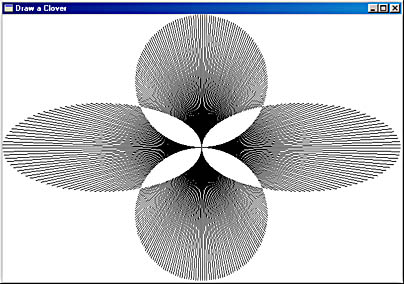
Figure 5-28. The CLOVER display, drawn using a complex clipping region.
Because regions always use device coordinates, the CLOVER program has to recreate the region every time it receives a WM_SIZE message. Years ago, the machines that ran Windows took several seconds to redraw this figure. Today's fast machines draw it nearly instantaneously.
CLOVER begins by creating four elliptical regions that are stored as the first four elements of the hRgnTemp array. Then the program creates three "dummy" regions:
hRgnTemp [4] = CreateRectRgn (0, 0, 1, 1) ; hRgnTemp [5] = CreateRectRgn (0, 0, 1, 1) ; hRgnClip = CreateRectRgn (0, 0, 1, 1) ;
The two elliptical regions at the left and right of the client area are combined:
CombineRgn (hRgnTemp [4], hRgnTemp [0], hRgnTemp [1], RGN_OR) ;
Similarly, the two elliptical regions at the top and bottom of the client area are combined:
CombineRgn (hRgnTemp [5], hRgnTemp [2], hRgnTemp [3], RGN_OR) ;
Finally these two combined regions are in turn combined into hRgnClip:
CombineRgn (hRgnClip, hRgnTemp [4], hRgnTemp [5], RGN_XOR) ;
The RGN_XOR identifier is used to exclude overlapping areas from the resultant region. Finally the six temporary regions are deleted:
for (i = 0 ; i < 6 ; i++) DeleteObject (hRgnTemp [i]) ;
The WM_PAINT processing is simple, considering the results. The viewport origin is set to the center of the client area (to make the line drawing easier), and the region created during the WM_SIZE message is selected as the device context's clipping region:
SetViewportOrg (hdc, xClient / 2, yClient / 2) ; SelectClipRgn (hdc, hRgnClip) ;
Now all that's left is drawing the lines—360 of them, spaced 1 degree apart. The length of each line is the variable fRadius, which is the distance from the center to the corner of the client area:
fRadius = hypot (xClient / 2.0, yClient / 2.0) ; for (fAngle = 0.0 ; fAngle < TWO_PI ; fAngle += TWO_PI / 360) { MoveToEx (hdc, 0, 0, NULL) ; LineTo (hdc, (int) ( fRadius * cos (fAngle) + 0.5), (int) (-fRadius * sin (fAngle) + 0.5)) ; } During processing of WM_DESTROY, the region is deleted:
DeleteObject (hRgnClip) ;
This is not the end of graphics programming in this book. Chapter 13 looks at printing, Chapters 14 and 15 at bitmaps, Chapter 17 at text and fonts, and Chapter 18 at metafiles.
EAN: 2147483647
Pages: 112