The Device Context
Before we begin drawing, let's examine the device context with more rigor than we did in Chapter 4.
When you want to draw on a graphics output device such as the screen or printer, you must first obtain a handle to a device context (or DC). In giving your program this handle, Windows is giving you permission to use the device. You then include the handle as an argument to the GDI functions to identify to Windows the device on which you wish to draw.
The device context contains many "attributes" that determine how the GDI functions work on the device. These attributes allow GDI functions to have just a few arguments, such as starting coordinates. The GDI functions do not need arguments for everything else that Windows needs to display the object on the device. For example, when you call TextOut, you need specify in the function only the device context handle, the starting coordinates, the text, and the length of the text. You don't need to specify the font, the color of the text, the color of the background behind the text, or the intercharacter spacing. These are all attributes that are part of the device context. When you want to change one of these attributes, you call a function that does so. Subsequent TextOut calls to that device context use the new attribute.
Getting a Device Context Handle
Windows provides several methods for obtaining a device context handle. If you obtain a video display device context handle while processing a message, you should release it before exiting the window procedure. After you release the handle, it is no longer valid. For a printer device context handle, the rules are not as strict. Again, we'll look at printing in Chapter 13.
The most common method for obtaining a device context handle and then releasing it involves using the BeginPaint and EndPaint calls when processing the WM_PAINT message:
hdc = BeginPaint (hwnd, &ps) ; [other program lines] EndPaint (hwnd, &ps) ;
The variable ps is a structure of type PAINTSTRUCT. The hdc field of this structure is the same handle to the device context that BeginPaint returns. The PAINSTRUCT structure also contains a RECT (rectangle) structure named rcPaint that defines a rectangle encompassing the invalid region of the window's client area. With the device context handle obtained from BeginPaint you can draw only within this region. The BeginPaint call also validates this region.
Windows programs can also obtain a handle to a device context while processing messages other than WM_PAINT:
hdc = GetDC (hwnd) ; [other program lines] ReleaseDC (hwnd, hdc) ;
This device context applies to the client area of the window whose handle is hwnd. The primary difference between the use of these calls and the use of the BeginPaint and EndPaint combination is that you can draw on your entire client area with the handle returned from GetDC. However, GetDC and ReleaseDC don't validate any possibly invalid regions of the client area.
A Windows program can also obtain a handle to a device context that applies to the entire window and not only to the window's client area:
hdc = GetWindowDC (hwnd) ; [other program lines] ReleaseDC (hwnd, hdc) ;
This device context includes the window title bar, menu, scroll bars, and frame in addition to the client area. Applications programs rarely use the GetWindowDC function. If you want to experiment with it, you should also trap the WM_NCPAINT ("nonclient paint") message, which is the message Windows uses to draw on the nonclient areas of the window.
The BeginPaint, GetDC, and GetWindowDC calls obtain a device context associated with a particular window on the video display. A much more general function for obtaining a handle to a device context is CreateDC:
hdc = CreateDC (pszDriver, pszDevice, pszOutput, pData) ; [other program lines] DeleteDC (hdc) ;
For example, you can obtain a device context handle for the entire display by calling
hdc = CreateDC (TEXT ("DISPLAY"), NULL, NULL, NULL) ; Writing outside your window is generally impolite, but it's convenient for some unusual applications. (Although this fact is not documented, you can also retrieve a device context for the entire screen by calling GetDC with a NULL argument.) In Chapter 13, we'll use the CreateDC function to obtain a handle to a printer device context.
Sometimes you need only to obtain some information about a device context and not do any drawing. In these cases, you can obtain a handle to an "information context" by using CreateIC. The arguments are the same as for the CreateDC function. For example,
hdc = CreateIC (TEXT ("DISPLAY"), NULL, NULL, NULL) ; You can't write to the device by using this information context handle.
When working with bitmaps, it can sometimes be useful to obtain a "memory device context":
hdcMem = CreateCompatibleDC (hdc) ; [other program lines] DeleteDC (hdcMem) ;
You can select a bitmap into the memory device context and use GDI functions to draw on the bitmap. I'll discuss these techniques in Chapter 14.
I mentioned earlier that a metafile is a collection of GDI function calls encoded in binary form. You can create a metafile by obtaining a metafile device context:
hdcMeta = CreateMetaFile (pszFilename) ; [other program lines] hmf = CloseMetaFile (hdcMeta) ;
During the time the metafile device context is valid, any GDI calls you make using hdcMeta are not displayed but become part of the metafile. When you call CloseMetaFile, the device context handle becomes invalid. The function returns a handle to the metafile (hmf). I'll discuss metafiles in Chapter 18.
Getting Device Context Information
A device context usually refers to a physical display device such as a video display or a printer. Often, you need to obtain information about this device, including the size of the display, in terms of both pixels and physical dimensions, and its color capabilities. You can get this information by calling the GetDeviceCap ("get device capabilities") function:
iValue = GetDeviceCaps (hdc, iIndex) ;
The iIndex argument is one of 29 identifiers defined in the WINGDI.H header file. For example, the iIndex value of HORZRES causes GetDeviceCaps to return the width of the device in pixels; a VERTRES argument returns the height of the device in pixels. If hdc is a handle to a screen device context, that's the same information you can get from GetSystemMetrics. If hdc is a handle to a printer device context, GetDeviceCaps returns the height and width of the printer display area in pixels.
You can also use GetDeviceCaps to determine the device's capabilities of processing various types of graphics. This is usually not important for dealing with the video display, but it becomes more important with working with printers. For example, most pen plotters can't draw bitmapped images and GetDeviceCaps can tell you that.
The DEVCAPS1 Program
The DEVCAPS1 program, shown in Figure 5-1, displays some (but not all) of the information available from the GetDeviceCaps function using a device context for the video display. In Chapter 13, I'll present a second, expanded version of this program, called DEVCAPS2, that gets information for the printer.
Figure 5-1. The DEVCAPS1 program.
DEVCAPS1.C /*--------------------------------------------------------- DEVCAPS1.C -- Device Capabilities Display Program No. 1 (c) Charles Petzold, 1998 ---------------------------------------------------------*/ #include <windows.h> #define NUMLINES ((int) (sizeof devcaps / sizeof devcaps [0])) struct { int iIndex ; TCHAR * szLabel ; TCHAR * szDesc ; } devcaps [] = { HORZSIZE, TEXT ("HORZSIZE"), TEXT ("Width in millimeters:"), VERTSIZE, TEXT ("VERTSIZE"), TEXT ("Height in millimeters:"), HORZRES, TEXT ("HORZRES"), TEXT ("Width in pixels:"), VERTRES, TEXT ("VERTRES"), TEXT ("Height in raster lines:"), BITSPIXEL, TEXT ("BITSPIXEL"), TEXT ("Color bits per pixel:"), PLANES, TEXT ("PLANES"), TEXT ("Number of color planes:"), NUMBRUSHES, TEXT ("NUMBRUSHES"), TEXT ("Number of device brushes:"), NUMPENS, TEXT ("NUMPENS"), TEXT ("Number of device pens:"), NUMMARKERS, TEXT ("NUMMARKERS"), TEXT ("Number of device markers:"), NUMFONTS, TEXT ("NUMFONTS"), TEXT ("Number of device fonts:"), NUMCOLORS, TEXT ("NUMCOLORS"), TEXT ("Number of device colors:"), PDEVICESIZE, TEXT ("PDEVICESIZE"), TEXT ("Size of device structure:"), ASPECTX, TEXT ("ASPECTX"), TEXT ("Relative width of pixel:"), ASPECTY, TEXT ("ASPECTY"), TEXT ("Relative height of pixel:"), ASPECTXY, TEXT ("ASPECTXY"), TEXT ("Relative diagonal of pixel:"), LOGPIXELSX, TEXT ("LOGPIXELSX"), TEXT ("Horizontal dots per inch:"), LOGPIXELSY, TEXT ("LOGPIXELSY"), TEXT ("Vertical dots per inch:"), SIZEPALETTE, TEXT ("SIZEPALETTE"), TEXT ("Number of palette entries:"), NUMRESERVED, TEXT ("NUMRESERVED"), TEXT ("Reserved palette entries:"), COLORRES, TEXT ("COLORRES"), TEXT ("Actual color resolution:") } ; LRESULT CALLBACK WndProc (HWND, UINT, WPARAM, LPARAM) ; int WINAPI WinMain (HINSTANCE hInstance, HINSTANCE hPrevInstance, PSTR szCmdLine, int iCmdShow) { static TCHAR szAppName[] = TEXT ("DevCaps1") ; HWND hwnd ; MSG msg ; WNDCLASS wndclass ; wndclass.style = CS_HREDRAW | CS_VREDRAW ; wndclass.lpfnWndProc = WndProc ; wndclass.cbClsExtra = 0 ; wndclass.cbWndExtra = 0 ; wndclass.hInstance = hInstance ; wndclass.hIcon = LoadIcon (NULL, IDI_APPLICATION) ; wndclass.hCursor = LoadCursor (NULL, IDC_ARROW) ; wndclass.hbrBackground = (HBRUSH) GetStockObject (WHITE_BRUSH) ; wndclass.lpszMenuName = NULL ; wndclass.lpszClassName = szAppName ; if (!RegisterClass (&wndclass)) { MessageBox (NULL, TEXT ("This program requires Windows NT!"), szAppName, MB_ICONERROR) ; return 0 ; } hwnd = CreateWindow (szAppName, TEXT ("Device Capabilities"), WS_OVERLAPPEDWINDOW, CW_USEDEFAULT, CW_USEDEFAULT, CW_USEDEFAULT, CW_USEDEFAULT, NULL, NULL, hInstance, NULL) ; ShowWindow (hwnd, iCmdShow) ; UpdateWindow (hwnd) ; while (GetMessage (&msg, NULL, 0, 0)) { TranslateMessage (&msg) ; DispatchMessage (&msg) ; } return msg.wParam ; } LRESULT CALLBACK WndProc (HWND hwnd, UINT message, WPARAM wParam, LPARAM lParam) { static int cxChar, cxCaps, cyChar ; TCHAR szBuffer[10] ; HDC hdc ; int i ; PAINTSTRUCT ps ; TEXTMETRIC tm ; switch (message) { case WM_CREATE: hdc = GetDC (hwnd) ; GetTextMetrics (hdc, &tm) ; cxChar = tm.tmAveCharWidth ; cxCaps = (tm.tmPitchAndFamily & 1 ? 3 : 2) * cxChar / 2 ; cyChar = tm.tmHeight + tm.tmExternalLeading ; ReleaseDC (hwnd, hdc) ; return 0 ; case WM_PAINT: hdc = BeginPaint (hwnd, &ps) ; for (i = 0 ; i < NUMLINES ; i++) { TextOut (hdc, 0, cyChar * i, devcaps[i].szLabel, lstrlen (devcaps[i].szLabel)) ; TextOut (hdc, 14 * cxCaps, cyChar * i, devcaps[i].szDesc, lstrlen (devcaps[i].szDesc)) ; SetTextAlign (hdc, TA_RIGHT | TA_TOP) ; TextOut (hdc, 14 * cxCaps + 35 * cxChar, cyChar * i, szBuffer, wsprintf (szBuffer, TEXT ("%5d"), GetDeviceCaps (hdc, devcaps[i].iIndex))) ; SetTextAlign (hdc, TA_LEFT | TA_TOP) ; } EndPaint (hwnd, &ps) ; return 0 ; case WM_DESTROY: PostQuitMessage (0) ; return 0 ; } return DefWindowProc (hwnd, message, wParam, lParam) ; } |
As you can see, this program is quite similar to the SYSMETS1 program shown in Chapter 4. To keep the code short, I didn't include scroll bars because I knew the information would fit on one screen. The results for a 256-color, 640-by-480 VGA are shown in Figure 5-2.
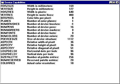
Figure 5-2. The DEVCAPS1 display for a 256-color, 640-by-480 VGA.
The Size of the Device
Suppose you want to draw a square with sides that are 1 inch in length. To do this, either you (the programmer) or Windows (the operating system) would need to know how many pixels corresponded to 1 inch on the video display. The GetDeviceCaps function helps you obtain information regarding the physical size of the output device, be it the video display or printer.
Video displays and printers are two very different devices. But perhaps the least obvious difference is how the word "resolution" is used in connection with the device. With printers, we often indicate a resolution in dots per inch. For example, most laser printers have a resolution of 300 or 600 dots per inch. However, the resolution of a video display is given as the total number of pixels horizontally and vertically, for example, 1024 by 768. Most people couldn't tell you the total number of pixels their printers display horizontally and vertically on a sheet of paper or the number of pixels per inch on their video displays.
In this book I'm going to use the word "resolution" in the strict sense of a number of pixels per metrical unit, generally an inch. I'll use the phrase "pixel size" or "pixel dimension" to indicate the total number of pixels that the device displays horizontally or vertically. The "metrical size" or "metrical dimension" is the size of the display area of the device in inches or millimeters. (For a printer page, this is not the whole size of the paper but only the printable area.) Dividing the pixel size by the metrical size gives you a resolution.
Most video displays used with Windows these days have screens that are 33 percent wider than they are high. This represents an aspect ratio of 1.33:1 or (as it's more commonly written) 4:3. Historically, this aspect ratio goes way back to when Thomas Edison was making movies. It remained the standard aspect ratio for motion pictures until various types of widescreen projection started to be used beginning in 1953. Television sets also have an aspect ratio of 4:3.
However, your Windows applications should not assume that the video display has a 4:3 aspect ratio. People who do mostly word processing sometimes prefer a video display that resembles the height and width of a sheet of paper. The most common alternative to a 4:3 display is a 3:4 display—essentially a standard display turned on its side.
If the horizontal resolution of a device equals the vertical resolution, the device is said to have "square pixels." Nowadays all video displays in common use with Windows have square pixels, but this was not always the case. (Nor should your applications assume that the video display always has square pixels.) When Windows was first introduced, the standard video adapter boards were the IBM Color Graphics Adapter (CGA), which had a pixel dimension area of 640 by 200 pixels; the Enhanced Graphics Adapter (EGA), which had a pixel dimension of 640 by 350 pixels; and the Hercules Graphics Card, which had a pixel dimension of 720 by 348 pixels. All these video boards used a display that had a 4:3 aspect ratio, but the number of pixels horizontally and vertically was not in the ratio 4:3.
It's quite easy for a user running Windows to determine the pixel dimensions of a video display. Run the Display applet in Control Panel, and select the Settings tab. In the area labeled Screen Area, you'll probably see one of these pixel dimensions:
- 640 by 480 pixels
- 800 by 600 pixels
- 1024 by 768 pixels
- 1280 by 1024 pixels
- 1600 by 1200 pixels
All of these are in the ratio 4:3. (Well, all except the 1280 by 1024 pixel size. This should probably be considered an annoying anomaly rather than anything more significant. As we'll see, all these pixel dimensions when combined with a 4:3 monitor are considered to yield square pixels.)
A Windows application can obtain the pixel dimensions of the display from GetSystemMetrics with the SM_CXSCREEN and SM_CYSCREEN arguments. As you'll note from the DEVCAPS1 program, a program can obtain the same values from GetDeviceCaps with the HORZRES ("horizontal resolution") and VERTRES arguments. This is a use of the word "resolution" that means the pixel size rather than the pixels per metrical unit.
That's the simple part of the device size. Now the confusion begins.
The first two device capabilities, HORZSIZE and VERTSIZE, are documented as "Width, in millimeters, of the physical screen" and "Height, in millimeters, of the physical screen" (in /Platform SDK/Graphics and Multimedia Services/GDI/Device Contexts/Device Context Reference/Device Context Functions/GetDeviceCaps). These seem like straightforward definitions until one begins to think through their implications. For example, given the nature of the interface between video display adapters and monitors, how can Windows really know the monitor size? And what if you have a laptop (in which the video driver conceivably could know the exact physical dimensions of the screen) and you attach an external monitor to it? And what if you attach a video projector to your PC?
In the 16-bit versions of Windows (and in Windows NT), Windows uses a "standard" display size for the HORZSIZE and VERTSIZE values. Beginning with Windows 95, however, the HORZSIZE and VERTSIZE values are derived from the HORZRES, VERTRES, LOGPIXELSX, and LOGPIXELSY values. Here's how it works.
When you use the Display applet of the Control Panel to select a pixel size of the display, you can also select a size of your system font. The reason for this option is that the font used for the 640 by 480 display may be too small to read when you go up to 1024 by 768 or beyond. Instead, you'll want a larger system font. These system font sizes are referred to on the Settings tab of the Display applet as Small Fonts and Large Fonts.
In traditional typography, the size of the characters in a font is indicated by a "point size." A point is approximately 1/72 inch and in computer typography is often assumed to be exactly 1/72 inch.
In theory, the point size of a font is the distance from the top of the tallest character in the font to the bottom of descenders in characters such as j, p, q, and y, excluding accent marks. For example, in a 10-point font this distance would be 10/72 inch. In terms of the TEXTMETRIC structure, the point size of the font is equivalent to the tmHeight field minus the tmInternalLeading field, as shown in Figure 5-3. (This figure is the same as Figure 4-3 in the last chapter.)
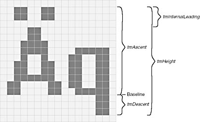
Figure 5-3. The small font and the TEXTMETRIC fields.
In real-life typography, the point size of a font is not so precisely related to the actual size of the font characters. The designer of the font might make the actual characters a bit larger or smaller than the point size would indicate. After all, font design is an art rather than a science.
The tmHeight field of the TEXTMETRIC structure indicates how successive lines of text should be spaced on the screen or printer. This can also be measured in points. For example, a 12-point line spacing indicates the baselines of successive lines of text should be 12/72 (or 1/6) inch apart. You don't want to use 10-point line spacing for a 10-point font because the successive lines of text could actually touch each other.
This book is printed with a 10-point font and 13-point line spacing. A 10-point font is considered comfortable for reading. Anything much smaller than 10 points would be difficult to read for long periods of time.
The Windows system font—regardless of whether it is the "small font" or the "large font" and regardless of what video pixel dimension you've selected—is assumed to be a 10-point font with a 12-point line spacing. I know this sounds odd. Why call the system fonts "small font" and "large font" if they're both 10-point fonts?
Here's the key: When you select the small font or the large font in the Display applet of the Control Panel, you are actually selecting an assumed video display resolution in dots per inch. When you select the small font, you are saying that you want Windows to assume that the video display resolution is 96 dots per inch. When you select the large font, you want Windows to assume that the video display resolution is 120 dots per inch.
Look at Figure 5-3 again. That's the small font, which is based on a display resolution of 96 dots per inch. I said it's a 10-point font. Ten points is 10/72 inch, which if you multiply by 96 dots per inch yields a result of (approximately) 13 pixels. That's tmHeight minus tmInternalLeading. The line spacing is 12 points, or 12/72 inch, which multiplied by 96 dots per inch yields 16 pixels. That's tmHeight.
Figure 5-4 shows the large font. This is based on a resolution of 120 dots per inch. Again, it's a 10-point font, and 10/72 times 120 dots per inch equals 16 pixels (if you round down), which is tmHeight minus tmInternalLeading. The 12-point line spacing is equivalent to 20 pixels, which is tmHeight. (As in Chapter 4, let me emphasize again that I'm showing you actual metrics so that you can understand how this works. Do not code these numbers in your programs.)
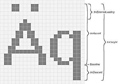
Figure 5-4. The large font and the FONTMETRIC fields.
Within a Windows program you can use the GetDeviceCaps function to obtain the assumed resolution in dots per inch that the user selected in the Display applet of the Control Panel. To get these values—which in theory could be different if the video display doesn't have square pixels—you use the indices LOGPIXELSX and LOGPIXELSY. The name LOGPIXELS stands for "logical pixels," which basically means "not the actual resolution in pixels per inch."
The device capabilities that you obtain from GetDeviceCaps with the HORZSIZE and VERTSIZE indices are documented (as I indicated earlier) as "Width, in millimeters, of the physical screen" and "Height, in millimeters, of the physical screen." These should be documented as a "logical width" and a "logical height," because the values are derived from the HORZRES, VERTRES, LOGPIXELSX, and LOGPIXELSY values. The formulas are
Horizontal Size (mm) = 25.4 × Horizontal Resolution (pixels)/ Logical Pixels X (dots per inch)
Vertical Size (mm) = 25.4 × Vertical Resolution (pixels)/ Logical Pixels Y (dots per inch)
The 25.4 constant is necessary to convert from inches to millimeters.
This may seem backward and illogical. After all, your video display has a size in millimeters that you can actually measure with a ruler (at least approximately). But Windows 98 doesn't care about that size. Instead it calculates a display size in millimeters based on the pixel size of the display the user selects and also the resolution the user selects for sizing the system font. Change the pixel size of your display and according to GetDeviceCaps the metrical size changes. How much sense does that make?
It makes more sense than you might suspect. Let's suppose you have a 17-inch monitor. The actual display size will probably be about 12 inches by 9 inches. Suppose you were running Windows with the minimum required pixel dimensions of 640 by 480. This means that the actual resolution is 53 dots per inch. A 10-point font—perfectly readable on paper—on the screen would be only 7 pixels in height from the top of the A to the bottom of the q. Such a font would be ugly and just about unreadable. (Ask people who ran Windows on the old Color Graphics Adapter.)
Now hook up a video projector to your PC. Let's say the projected video display is a 4 feet wide and 3 feet high. That same 640 by 480 pixel dimension now implies a resolution of about 13 dots per inch. It would be ridiculous to try displaying a 10-point font under such conditions.
A 10-point font should be readable on the video display because it is surely readable when printed. The 10-point font thus becomes an important frame of reference. When a Windows application is guaranteed that a 10-point screen font is of average size, it can then display smaller (but still readable) text using an 8-point font and larger text using fonts of point sizes greater than 10. Thus, it makes sense that the video resolution (in dots per inch) be implied by the pixel size of that 10-point font.
In Windows NT, however, an older approach is used in defining the HORZSIZE and VERTSIZE values. This approach is consistent with 16-bit versions of Windows. The HORZRES and VERTRES values still indicate the number of pixels horizontally and vertically (of course), and LOGPIXELSX and LOGPIXELSY are still related to the font that you choose when setting the video resolution in the Display applet of the Control Panel. As with Windows 98, typical values of LOGPIXELSX and LOGPIXELSY are 96 and 120 dots per inch, depending on whether you select a small font or large font.
The difference in Windows NT is that the HORZSIZE and VERTSIZE values are fixed to indicate a standard monitor size. For common adapters, the values of HORZSIZE and VERTSIZE you'll obtain are 320 and 240 millimeters, respectively. These values are the same regardless of what pixel dimension you choose. Therefore, these values are inconsistent with the values you obtain from GetDeviceCaps with the HORZRES, VERTRES, LOGPIXELSX, and LOGPIXELSY indices. However, you can always calculate HORZSIZE and VERTSIZE values like those you'd obtain under Windows 98 by using the formulas shown earlier.
What if your program needs the actual physical dimensions of the video display? Probably the best solution is to actually request them of the user with a dialog box.
Finally, three other values from GetDeviceCaps are related to the video dimensions. The ASPECTX, ASPECTY, and ASPECTXY values are the relative width, height, and diagonal size of each pixel, rounded to the nearest integer. For square pixels, the ASPECTX and ASPECTY values will be the same. Regardless, the ASPECTXY value equals the square root of the sum of the squares of the ASPECTX and ASPECTY values, as you'll recall from Pythagoras.
Finding Out About Color
A video display capable of displaying only black pixels and white pixels requires only one bit of memory per pixel. Color displays require multiple bits per pixels. The more bits, the more colors; or more specifically, the number of unique simultaneous colors is equal to 2 to the number of bits per pixel.
A "full color" video display resolution has 24 bits per pixel—8 bits for red, 8 bits for green, and 8 bits for blue. Red, green, and blue are known as the "additive primaries." Mixes of these three primary colors can create many other colors, as you can verify by peering at your color video display through a magnifying glass.
A "high color" display resolution has 16 bits per pixel, generally 5 bits for red, 6 bits for green, and 5 bits for blue. More bits are used for the green primary because the human eye is more sensitive to variations in green than to the other two primaries.
A video adapter that displays 256 colors requires 8 bits per pixel. However, these 8-bit values are generally indices into a palette table that defines the actual colors. I'll discuss this more in Chapter 16.
Finally, a video board that displays 16 colors requires 4 bits per pixel. These 16 colors are generally fixed as dark and light versions of red, green, blue, cyan, magenta, yellow, two shades of gray, black, and white. These 16 colors date back to the old IBM CGA.
Only in some odd programming jobs is it necessary to know how memory is organized on the video adapter board, but GetDeviceCaps will help you determine that. Video memory can be organized either with consecutive color bits for each pixel or with each color bit in a separate plane of memory. This call returns the number of color planes:
iPlanes = GetDeviceCaps (hdc, PLANES) ;
and this call returns the number of color bits per pixel:
iBitsPixel = GetDeviceCaps (hdc, BITSPIXEL) ;
One of these calls will return a value of 1. The number of colors that can be simultaneously rendered on the video adapter can be calculated by the formula
iColors = 1 << (iPlanes * iBitsPixel) ;
This value may or may not be the same as the number of colors obtainable with the NUMCOLORS argument:
iColors = GetDeviceCaps (hdc, NUMCOLORS) ;
I mentioned that 256-color video adapters use color palettes. In that case, GetDeviceCaps with the NUMCOLORS index returns the number of colors reserved by Windows, which will be 20. The remaining 236 colors can be set by a Windows program using the palette manager. For high-color and full-color display resolutions, GetDeviceCaps with the NUMCOLORS index often returns -1, making it a generally unreliable function for determining this information. Instead, use the iColors formula shown earlier that uses the PLANES and BITSPIXEL values.
In most GDI function calls, you use a COLORREF value (which is simply a 32-bit unsigned long integer) to refer to a particular color. The COLORREF value specifies a color in terms of red, green, and blue intensities and is often called an "RGB color." The 32 bits of the COLORREF value are set as shown in Figure 5-5.
Figure 5-5. The 32-bit COLORREF value.
Notice that the most-significant 8 bits are zero, and that each primary is specified as an 8-bit value. In theory, a COLORREF value can refer to 224 or about 16 million colors.
The Windows header file WINGDI.H provides several macros for working with RGB color values. The RGB macro takes three arguments representing red, green, and blue values and combines them into an unsigned long:
#define RGB(r,g,b) ((COLORREF)(((BYTE)(r) | \ ((WORD)((BYTE)(g)) << 8)) | \ (((DWORD)(BYTE)(b)) << 16)))
Notice that the order of the three arguments is red, green, and blue. Thus, the value
RGB (255, 255, 0)
is 0x0000FFFF or yellow—the combination of red and green. When all three arguments are set to 0, the color is black; when all the arguments are set to 255, the color is white. The GetRValue, GetGValue, and GetBValue macros extract the primary color values from a COLORREF value. These macros are sometimes handy when you're using a Windows function that returns RGB color values to your program.
On 16-color or 256-color video adapters, Windows can use "dithering" to simulate more colors than the device can display. Dithering involves a small pattern that combines pixels of different colors. You can determine the closest pure nondithered color of a particular color value by calling GetNearestColor:
crPureColor = GetNearestColor (hdc, crColor) ;
The Device Context Attributes
As I noted above, Windows uses the device context to store "attributes" that govern how the GDI functions operate on the display. For instance, when you display some text using the TextOut function, you don't have to specify the color of the text or the font. Windows uses the device context to obtain this information.
When a program obtains a handle to a device context, Windows sets all the attributes to default values. (However, see the next section for how to override this behavior.) The following table shows many of the device context attributes supported under Windows 98, along with the default values and the functions to change or obtain their values.
| Device Context Attribute | Default | Function(s) to Change | Function to Obtain |
| Mapping Mode | MM_TEXT | SetMapMode | GetMapMode |
| Window Origin | (0, 0) | SetWindowOrgEx OffsetWindowOrgEx | GetWindowOrgEx |
| Viewport Origin | (0, 0) | SetViewportOrgEx OffsetViewportOrgEx | GetViewportOrgEx |
| Window Extents | (1, 1) | SetWindowExtEx SetMapMode ScaleWindowExtEx | GetWindowExtEx |
| Viewport Extents | (1, 1) | SetViewportExtEx SetMapMode ScaleViewportExtEx | GetViewportExtEx |
| Pen | BLACK_PEN | SelectObject | SelectObject |
| Brush | WHITE_BRUSH | SelectObject | SelectObject |
| Font | SYSTEM_FONT | SelectObject | SelectObject |
| Bitmap | None | SelectObject | SelectObject |
| Current Position | (0, 0) | MoveToEx LineTo PolylineTo PolyBezierTo | GetCurrentPositionEx |
| Background Mode | OPAQUE | SetBkMode | GetBkMode |
| Background Color | White | SetBkColor | GetBkColor |
| Text Color | Black | SetTextColor | GetTextColor |
| Drawing Mode | R2_COPYPEN | SetROP2 | GetROP2 |
| Stretching Mode | BLACKONWHITE | SetStretchBltMode | GetStretchBltMode |
| Polygon Fill Mode | ALTERNATE | SetPolyFillMode | GetPolyFillMode |
| Intercharacter Spacing | 0 | SetTextCharacterExtra | GetTextCharacterExtra |
| Brush Origin | (0, 0) | SetBrushOrgEx | GetBrushOrgEx |
| Clipping Region | None | SelectObject SelectClipRgn IntersectClipRgn OffsetClipRgn ExcludeClipRect SelectClipPath | GetClipBox |
Saving Device Contexts
Normally when you call GetDC or BeginPaint, Windows gives you a device context with default values for all the attributes. Any changes you make to the attributes are lost when the device context is released with the ReleaseDC or EndPaint call. If your program needs to use nondefault device context attributes, you'll have to initialize the device context every time you obtain a new device context handle:
case WM_PAINT: hdc = BeginPaint (hwnd, &ps) ; [initialize device context attributes] [paint client area of window] EndPaint (hwnd, &ps) ; return 0 ;
Although this approach is generally satisfactory, you might prefer that changes you make to the attributes be saved when you release the device context so that they will be in effect the next time you call GetDC or BeginPaint. You can accomplish this by including the CS_OWNDC flag as part of the window class style when you register the window class:
wndclass.style = CS_HREDRAW | CS_VREDRAW | CS_OWNDC ;
Now each window that you create based on this window class will have its own private device context that continues to exist when the window is destroyed. When you use the CS_OWNDC style, you need to initialize the device context attributes only once, perhaps while processing the WM_CREATE message:
case WM_CREATE: hdc = GetDC (hwnd) ; [initialize device context attributes] ReleaseDC (hwnd, hdc) ;
The attributes continue to be valid until you change them.
The CS_OWNDC style affects only the device contexts retrieved from GetDC and BeginPaint and not device contexts obtained from the other functions (such as GetWindowDC). Employing CS_OWNDC was once discouraged because it required some memory overhead; nowadays it can improve performance in some graphics-intensive Windows NT applications. Even if you use CS_OWNDC, you should still release the device context handle before exiting the window procedure.
In some cases you might want to change certain device context attributes, do some painting using the changed attributes, and then revert to the original device context. To simplify this process, you save the state of a device context by calling
idSaved = SaveDC (hdc) ;
Now you can change some attributes. When you want to return to the device context as it existed before the SaveDC call, you use
RestoreDC (hdc, idSaved) ;
You can call SaveDC any number of times before you call RestoreDC.
Most programmers use SaveDC and RestoreDC in a different manner, however, much like PUSH and POP instructions in assembly language. When you call SaveDC, you don't need to save the return value:
SaveDC (hdc) ;
You can then change some attributes and call SaveDC again. To restore the device context to a saved state, call
RestoreDC (hdc, -1) ;
This restores the device context to the state saved by the most recent SaveDC function.
EAN: 2147483647
Pages: 112