The Drawing API
| | ||
| | ||
| | ||
Just so I dont lose anyone , let me tell you right off the bat what an API is. It stands for application programming interface. Generally , API refers to a set of methods and properties that you can use in your program to access a certain set of related behaviors and properties. The drawing API refers to the properties and methods that allow you to draw lines, curves, fills, gradient fills, and so on with ActionScript. This API has surprisingly few methods, but there is a lot to know about them and a lot of neat tricks you can do with them.
The drawing API was introduced in Flash MX. Prior to that, all graphical content had to be drawn in the authoring environment. With the drawing API, a lot more became possible.
Because of the drawing limitations in earlier versions of Flash, people thought up ingen ious ways to do dynamic drawing. One of the best examples was the 45-degree line movie clip. This consisted of a single movie clip in the library, set to export so that it could be attached at runtime or placed on stage somewhere so it could be duplicated . It contained a simple line drawn from 0, 0 to 100, 100. At runtime, to draw a line between any two points, you would create a new instance of this line clip, position it on the first point, and scale it so it that it fit between the first and second points. While this technique had some drawbacks, such as not allowing for fills or different widths of lines, it was surprisingly effi cient, and was the way that almost all dynamic drawing was done prior to Flash MX.
Beginning with Flash MX, you got the following methods:
-
clear()
-
lineStyle(width, color , alpha)
-
moveTo(x, y)
-
lineTo(x, y)
-
curveTo(x1, y1, x2, y2)
-
beginFill(color, alpha)
-
endFill()
-
beginGradientFill(fillType, colors, alphas, ratio, matrix)
In Flash 8, several enhancements were added to the lineStyle and beginGradientFill methods. It also introduced the beginBitmapFill and lineGradientStyle methods. As this is just a quick overview, Im not going to go into the newer methods and syntax. But be assured that what you see here will work just fine in Flash 6, 7, and 8.
The drawing API methods are methods of every movie clip object, so a method can be called like this:
myMovieClip.lineTo(100, 100);
Lets look at each of these methods and see some examples of their basic use.
Removing drawing with clear
clear is the simplest method of them all. It simply removes any previously drawn lines, curves, or fills from the movie clip. Note that it will affect only graphics that were created using other drawing API methods. In other words, if you drew a shape on stage in the authoring environment, calling clear() at runtime would not affect that shape.
Use of the clear method has an important and somewhat unexpected effect on drawing efficiency. In the drawing API, it happens that the more you draw in a particular movie clip, the slower it goes. For a few dozen shapes , the slowdown is not noticeable, but little by little, each new shape takes longer and longer to draw. Even if the new shape completely covers and obliterates everything else, the vector information for those older shapes is still there and will be completely redrawn each time. This can be important in animation, where you are redrawing almost the same thing over and over. Using clear handles this by completely removing all prior vector information from the clip.
Setting line appearance with lineStyle
With the lineStyle(width, color, alpha) method, you set up the appearance of all subsequently drawn lines. This command has no effect on previously drawn lines. In fact, other than clearing them, or drawing something else on top of them, there is no way of affecting or changing lines or fills that have been drawn. Once they are there, thats that.
The parameters for this method are pretty self-explanatory, but lets review them quickly:
-
width : The width of the line in pixels. The only valid values are zero or positive integers. Although you can pass in decimal values, they will be rounded off to the nearest positive integer. If you pass in zero or a negative value, Flash will draw a 1-pixel thick line.
-
color : The color you want the line to be. This is in a decimal or hex format, as described earlier in this chapter.
-
alpha : The transparency of the lines. This can be from 0 to 100, representing a percent of opacity. A setting of 100 is obviously fully opaque , and 0 is fully transparent or invisible.
Depending on which Flash version you are using, some of these parameters are optional. You can say lineStyle(1) and get a 1-pixel thick, black line, with all the other default parameters. But its become my habit to always specify the first three parameters, even if Im using the default values. So, in this book, youll often see lineStyle(1, 0, 100) . Actually, even the first parameter is optional. If you leave off the width, just calling lineStyle() , the line style will be cleared, and youll get an invisible line. This is the same as if you had started issuing drawing commands without setting the line style: You wont see any lines.
Another little fact that often trips people up is that the clear method clears not only the current drawing, but the current line style settings as well. If you set up a custom style, draw some lines into a movie clip, and then clear them, youll need to reset your line style before drawing anything else. Otherwise, youll be back to drawing zero-width (invisible) lines again.
Drawing lines with lineTo and moveTo
There are a couple of different ways to implement line drawing in a graphics language. One is to have a line command that takes a starting point and an ending point, and draws a line between them. The other way is to have a lineTo command that takes a single point: the ending point of the line. This is how ActionScript works. So, if youre drawing a line to some point, where are you drawing it from ? Well, if you havent drawn anything yet, youll be drawing from the point 0, 0 of whatever graphics object you are drawing into. Say you just type this line in a movie:
lineTo(100, 100);
Youll see a line going from the top-left corner (0, 0), to 100, 100 ( assuming youve set a line style). After youve drawn at least one line, the ending point for that line will be the starting point for the next line. Finally, you can use the moveTo method to specify a new starting point for the next line.
Think of the drawing API as a robot holding a pen on a piece of paper. When you start, the pen is at 0, 0. When you tell it to draw a line to a point, it just moves the pen across the paper to that new point. For each new line, it just moves from wherever it left off, to the next new point. The moveTo method is like saying, OK, now lift up the pen and move it to this next point. Although issuing a moveTo command does not result in any new graphic content, it will affect how the next graphics command is carried out. Unless you specifically want to draw your first line from 0, 0, you will generally call moveTo as your first drawing command to place the drawing API pen where you want to begin.
You now have enough commands under your belt to do something serious. Lets create a simple drawing application. This program will rely completely on the drawing API for its content, so you dont need to create any movie clip symbols beforehand. In fact, all you need to do is type the following code in the Actions panel for frame 1 of a new movie:
init(); function init() { lineStyle(1, 0, 100); } function onMouseDown():Void { moveTo(_xmouse, _ymouse); onMouseMove = draw; } function onMouseUp():Void { delete onMouseMove } function draw():Void { lineTo(_xmouse, _ymouse); } You can find this file among the books downloadable files (available from www.friendsofed.com) as ch04_01.fla . Ill go through it line by line. In addition to the drawing functions, this program makes pretty good use of event handlers (discussed in Chapter 2).
First, the code calls init , where the line style is set to a 1-pixel black linesimple enough.
Then theres the onMouseDown method. This gets called whenever the user presses a mouse button. Generally, this means the user wants to start drawing a line at the current mouse cursor position. Well, thats exactly what this function does. It puts the virtual pen down at the mouse location by calling moveTo and passing in the mouse coordinates. It then assigns a handler function for onMouseMove .
At this point, every time the user moves the mouse, the draw function is called. And what does that do? Not too much, although its the meat of the program. It just draws a line to the current mouse location.
Finally, theres the onMouseUp handler. This removes the onMouseMove handler so that no more drawing will happen.
OK, you have a neat little drawing program there. You could probably set up some simple controls to make it a full-featured drawing application without too much effort. Just create some variables for color and width , and create some buttons or other controls to change them, and call the lineStyle method again with the new values. Oh, and throw in a button that calls the clear method. Im going to leave that as an exercise for you to do on your own, if you are interested. Meanwhile, Im going to dive back into the rest of the drawing API.
Drawing curves with curveTo
The next drawing function, curveTo(x1, y1, x2, y2) , starts off the same as lineTo , in that it begins its drawing at the point where the last drawing ended, at the point where the last moveTo command moved the pen to, or at 0, 0 if no drawing has been done yet. It also makes use of lineStyle in exactly the same way as moveTo . The only difference is the shape of the line drawn.
As you can see, curveTo takes two points. The first one is a control point that affects the shape of the curve. The second point is the ending point of the curve. The formula used is a standard formula for what is called a quadratic Bezier curve. This formula calculates a curve from one point to another, which curves towards the control point. Note that the curve will not touch the control point. Its more like the curve is attracted to it.
Lets see it in action. Start a new FLA document and enter the following code in frame 1 (you can find this file listed as ch04_02.fla ):
var x0:Number = 100; var y0:Number = 200; var x2:Number = 300; var y2:Number = 200; function onEnterFrame(Void):Void { var x1:Number = _xmouse; var y1:Number = _ymouse; clear(); lineStyle(1, 0, 100); moveTo(x0, y0); curveTo(x1, y1, x2, y2); lineStyle(1, 0, 40); lineTo(_xmouse, _ymouse); lineTo(x0, y0); } Test the file and move your mouse around. The file uses two preset points for the beginning and ending points, and uses the mouse position for the control point. Notice that the curve never actually reaches the control point, but gets about halfway there.
Curving through the control point
Now, say you actually wanted to have the curve hit the control point. Well, heres another toolbox tip. You can use the following formula to calculate the actual control point so that the curve will go through the point you specify. Again, youll be starting out with x0 , y0 and x2 , y2 as the end points, and x1, y1 as the control point. Ill call the point you want the curve to go through, xt , yt ( t for target). In other words, if you want the curve to be drawn through xt , yt , what x1 , y1 do you need to use? Heres the formula:
x1 = xt * 2 (x0 + x2) / 2; y1 = yt * 2 (y0 + y2) / 2;
Basically, you just multiply the target by two, and subtract the average of the starting and ending point. If you want, you can graph it all out and see exactly how it works. Or, you can just test it, see that it works, and have faith that it always will.
Lets look at the formula in action, using the mouse coordinates as xt , yt . Heres the code for frame 1, which you can find in ch04_03.fla .
var x0:Number = 100; var y0:Number = 200; var x2:Number = 300; var y2:Number = 200; function onEnterFrame(Void):Void { var x1 = _xmouse * 2 - (x0 + x2) / 2; var y1 = _ymouse * 2 - (y0 + y2) / 2; clear(); lineStyle(1, 0, 100); moveTo(x0, y0); curveTo(x1, y1, x2, y2); } Only the lines that find x1 and y1 change.
Creating multiple curves
The next direction youre probably looking at going is creating multiple curves, where instead of a single curve, you have a long line that curves smoothly in several directions. First, Ill show you the wrong way of going about it, which is the way I originally tried it. Basically, you start out with a number of points, draw a curve from the first through the second to the third, then through the fourth to the fifth, then through the sixth to the seventh, and so on. Here it is in code (in ch04_04.fla ):
init(); function init() { // first set up an array of random points var points:Array = new Array(); for (var i = 0; i < 9; i++) { points[i] = new Object(); points[i].x = Math.random() * Stage.width; points[i].y = Math.random() * Stage.height; } lineStyle(1, 0, 100); // now move to the first point moveTo(points[0].x, points[0].y); // and loop through each next successive pair for (i = 1; i < points.length; i += 2) { curveTo(points[i].x, points[i].y, points[i + 1].x, points[i + 1].y); } } The first for loop in the init method just sets up an array of nine points. Each point is an object with an x and y property, and they are randomly thrown around the stage. Of course, in a real program, your points might not be random. I just used that method for quick setup.
Then the line style is set, and the pen is moved to the first point. The next for loop starts at one and increments by two each time, so it draws a curve through point one to two, then through three to four, then through five to six, and then through point seven to point eight. The loop will stop there, which is perfect because point eight is the last one. You also might notice that there must be a minimum of three points, and the number of points must be odd.
It all seems fine until you test it. As shown in Figure 4-1, it doesnt look very curvy at all. In fact, it often looks a bit spiky. The problem is that there is no coordination between one curve and the next, except that they share a point.
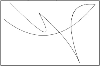
Figure 4-1: Multiple curves, the wrong way. You can plainly see where one curve ends and the next begins.
Youre going to have to plug in a few more points to make it work right. Heres the strategy: Between each set of two points, you need a new point that sits exactly in the middle. You then use these as the starting and ending points for each curve, and use the original points as the control points.
Figure 4-2 illustrates the solution. In the figure, the white dots are the original points, and the black dots are the in-between points. There are three curveTo methods here, which Ive given different colors so you can see where they start and end. (Figure 4-2 is actually a screenshot from a file called multicurvedemo.fla , which you can download from this books page on www.friendsofed.com.)
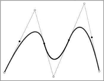
Figure 4-2: Multiple curves with midpoints
Notice in Figure 4-2 that the first and last midpoints are not used, and the first and last original points remain terminal points for the curves. You really need to make in-between points only for the second point up to the second-to-last point. Heres an updated version of the previous example for the random curves (found in ch04_05.fla ):
init(): function init() { var points:Array = new Array(); for (var i = 0; i < 9; i++) { points[i] = new Object(); points[i].x = Math.random() * Stage.width; points[i].y = Math.random() * Stage.height; } lineStyle(1, 0, 100); moveTo(points[0].x, points[0].y); for (i = 1; i < points.length - 2; i++) { var xc:Number = (points[i].x + points[i + 1].x) / 2; var yc:Number = (points[i].y + points[i + 1].y) / 2; curveTo(points[i].x, points[i].y, xc, yc); } } Note that in the new code, the for loop starts at 1 and ends at points.length - 2 . This prevents it from processing the first and last pairs of points. What it does is create a new x, y point, which is the average of the next two points in the array. Then it draws a curve through the next array point, to the new average point. When the loop ends, the index, i , will still be pointing to the second-to-last element. Thus, you can draw a curve through that to the last point.
This time, you will come up with a nice smooth shape, rather than those spikes, as shown in Figure 4-3. Also note that you are not limited to an odd number of original points any more. As long as you start with at least three points, youll be fine.
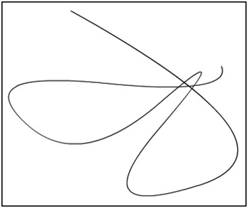
Figure 4-3: Smooth multiple curves
As a bit of a variation on a theme, the following code (found in ch04_06.fla ) creates a closed curve using the same technique. Basically, it computes an initial midpoint, which is the average of the first and last points, and moves to that. Then it loops through all the rest, figuring midpoints for each one, finally drawing its last curve back to the initial midpoint .
init(); function init() { var points:Array = new Array(); for (var i = 0; i < 9; i++) { points[i] = new Object(); points[i].x = Math.random() * Stage.width; points[i].y = Math.random() * Stage.height; } var xc1:Number = (points[0].x + points[points.length - 1].x) / 2; var yc1:Number = (points[0].y + points[points.length - 1].y) / 2; lineStyle(1, 0, 100); moveTo(xc1, yc1); for (i = 0; i < points.length - 1; i++) { var xc:Number = (points[i].x + points[i + 1].x) / 2; var yc:Number = (points[i].y + points[i + 1].y) / 2; curveTo(points[i].x, points[i].y, xc, yc); } curveTo(points[i].x, points[i].y, xc1, yc1); } Figure 4-4 shows the result.
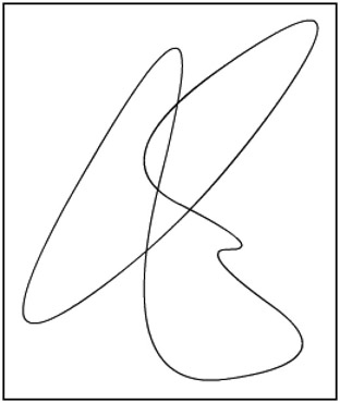
Figure 4-4: Multiple closed curves
Creating shapes with beginFill and endFill
The beginFill(color, alpha) method is so simple that theres not really too much to say about it. You can issue a beginFill command almost any time during the process of drawing. Flash will compute a shape beginning with wherever the drawing location happens to be and ending wherever the drawing location is when the endFill command is issued or, if it never is, wherever the location is when the code completes for that frame and the frame is rendered. Generally, though, the sequence is as follows :
-
moveTo
-
lineStyle (if any)
-
beginFill
-
A series of lineTo and curveTo methods, ending at the original point moved to
-
endFill
Actually, you can use the first three methods in just about any order without affecting what is drawn. You dont need to specify a line style. Remember that if you do not specify a line style, you get an invisible line, which is perfectly valid for drawing fills. Its also fine to draw both at the same time.
If you do not draw a line back to the original point from which you started, Flash will draw it for you in order to close the shape as soon as you call endFill . This final line will be drawn with whatever line style is present at the time you call endFill . However, it is definitely a good practice to get into the habit of finishing your own shapes. Not only are you guaranteed that the last line will be drawn even if Macromedia decides to change that particular behavior, but another person who looks at your code later will know that you actually did intend to draw the shape.
Go ahead and play around with drawing fills. You can even use the closed curve example from the previous section ( ch04_06.fla ), as that is already generating a closed shape. Just throw in a beginFill statement anywhere before the first curveTo say, beginFill(0xff00ff, 100); , which will create a bright purple filland finish off the code with endFill(); .
If you did this, Im sure you noticed that, where sections of the curve cross over itself, the fill kind of disappears. Theres not much you can do about that, but for the most part, youll probably be drawing shapes that dont intersect like that anyway. On the other hand, once you get used to how it works, you can use that behavior to create some interesting shapes.
Creating gradient fills with beginGradientFill
Now we come to the monster function of the drawing API: beginGradientFill(fillType, colors, alphas, ratio, matrix) . In many senses, this works in the same way as beginFill ; it has the same quirks and behaviors, and you always end it with the same old endFill . The big difference is in how the fill looks. I feel like I shouldnt have to say that beginGradientFill creates a gradient fill, but then again, I feel like Id be leaving something out if I didnt say it. So there you go.
A gradient fill is basically a fill of at least two colors. One part of the shape starts out with one color, and it slowly blends into another color, perhaps moving through one or several other predefined colors on its way.
Specifying the fill type
You can create two kinds of gradient fills: linear and radial. In a linear fill, the gradient of colors lies along a line from one point to another. By default, that line goes left to right, but you can make it go up and down or at any other angle. Figure 4-5 shows a few examples of linear fills.
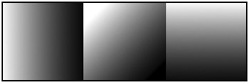
Figure 4-5: Linear fills
In order to see a linear fill, you need at least two different colors. If thats all you specify, the fill will blend from the first to the second. If you specify more colors, the fill will blend smoothly from the first, to the second, to the third, and so on until it hits the last one.
A radial fill works with pretty much all the same parameters that a linear fill uses, but interprets them a bit differently, creating a gradient that starts in the center of the space you define and radiates outward in all directions, creating a circle or oval. The first color you specify will be used as the center of the circle, and the final color will be the outline of the circle. The only item that is not needed is the angle. Figure 4-6 shows an example of a radial fill.
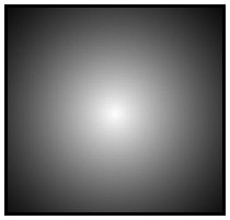
Figure 4-6: A radial fill
So, for the beginGradientFill(fillType, colors, alphas, ratios, matrix) method, the first parameter is fillType . Thats pretty simple. Its a string that can contain one of two values: "linear" or "radial" . You get what you ask for.
Setting the colors, alphas, and ratios
Along with the colors parameterto specify the colors, of courseyou can also specify the position of each color in the fill by assigning it a number from 0 to 255, where 0 is the start of the fill and 255 is the end. These numbers , one for each color, are known as the ratios of the fill. Thus, if you wanted to make a two-color fill, youd probably specify 0 and 255 as the ratios . To make an even blend of three colors, you could say 0, 128, 255. This would put the second color exactly in the middle of the other two. If you did something like 0, 20, 255, the first color would almost immediately blend into the second, and then very slowly blend into the third. Remember that these are not pixel values, but fractions of 255.
You can also specify the transparency of each color in the blend. This is known as alpha and can be from 0 to 100. If you dont want any transparency, you can make each alpha 100. If you set the first alpha to 100 and the last to 0, the gradient will not only blend the colors, but will smoothly fade out. This can be useful for creating soft shadows.
Each one of these arguments is an array. This makes sense, because you are probably going to be passing in at least two colors, alphas, and ratios, and possibly many more. You could create a new array and populate it with your values for each parameter, like so:
var colors:Array = new Array(); colors[0] = 0xffffff; colors[1] = 0x000000;
But theres a much easier way to do it. You can create and populate an array on the fly by listing the elements you want in it between square brackets, separated by commas:
var colors:Array = [0xffffff, 0x000000];
In fact, you dont even need to make a colors variable. You can plug that array right into the beginGradientFill statement as an argument. Thus, you can get something like this:
beginGradientFill("linear", [0xffffff, 0x000000], [100, 100], [0, 255], matrix); This defines two colors, two alpha values (both 100%), and start and end ratio values, so the gradient will start as white and blend into black at the end. Of course, you can create variables for each parameter if you want, and if you are defining a lot of colors, it will be clearer that way. The one caveat here is that these three arrays must all contain the same amount of elements. If you define three colors, you must have three alphas and three ratios. If any one contains more or less than the others, its going to fail silentlyno gradient, no fill, no error message.
All you need now is the start and end position and the angle of the fill. As you might have guessed, thats what the mysterious matrix parameter is for.
Creating the matrix
A matrix is usually a two-dimensional grid of values used for calculating various values. Matrices are used extensively in graphics for rotating, scaling, and moving things. Thats exactly what youre doing here with the gradient. You need to position it, size it, and possibly rotate it. To use the matrix, you need to create a matrix object. This is a generic object with nine properties: a through i . These create a three-by-three matrix, which Flash can use to position, size, and rotate your gradient.
Fortunately, Macromedia gives you a much easier way to use the matrix. Again, you create an object and give it some properties. But rather than completely nondescriptive names like a , b , and c , the property names are: matrixType , x , y , w , h , and r . The matrixType is simply a string, which must be set to "box" ; x and y are the start position of the gradient; w and h are the width and height; and r is the rotation (in radians). You generally want to set the x and y values to the top-left position of your fill, and the w and h values to the size of your fill. Similar to the way you can create an array with square brackets, you can create an object with curly brackets. So, you can do something like this:
var matrix:Object = {matrixType:"box", x:0, y:0, w:100, h:100, r:Math.PI/2}; Again, you could plug this right into the beginGradientFill function call, but its already kind of long, so I usually like to create the matrix as a separate variable and pass it in that way.
Lets see it in action. Heres some code, which you can find in ch04_07.fla :
init(); function init() { lineStyle(1, 0, 100); var colors:Array = [0xffffff, 0xff0000]; var alphas:Array = [100, 100]; var ratios:Array = [0, 255]; var matrix:Object = {matrixType:"box", w:100, h:100, x:0, y:0, r:0}; beginGradientFill("linear", colors, alphas, ratios, matrix); moveTo(0, 0); lineTo(100, 0); lineTo(100, 100); lineTo(0, 100); lineTo(0, 0); endFill(); } When you test this, youll see a nice white-to-red gradient square. Now lets draw the square in a different location, by changing the drawing code so you have the following code (in gradient2.fla ):
moveTo(100, 100); lineTo(200, 100); lineTo(200, 200); lineTo(100, 200); lineTo(100, 100);
Now your square is all red. What happened ? Well, the gradient starts at 0 on the x axis, and its only 100 pixels wide, so at the point your square begins, the gradient has already reached full red, and its red from there on out. So again, you are going to want the x, y of the matrix to be at the top-left point of your shape, like so (in the ch04_08.fla file):
var matrix:Object = {matrixType:"box", w:100, h:100, x:100, y:100, r:0}; Here, the x, y is the same as the start of the square. Using the same square. You can now play around with the matrix and gradient fill setting to see what kind of effects you can create. First, try three colors:
var colors:Array = [0xffffff, 0x0000ff, 0xff0000]; var alphas:Array = [100, 100, 100]; var ratios:Array = [0, 128, 255];
Dont forget the alphas and ratios. Move the middle ratio around to see how that affects the gradient. Instead of 128, try 64 or 220.
The next example is a straight alpha blend. The colors are the same; only the alpha changes:
var colors:Array = [0x000000, 0x000000]; var alphas:Array = [100, 0]; var ratios:Array = [0, 255];
Try changing the angle now. Heres a 45-degree angle:
var matrix:Object = {matrixType:"box", w:100, h:100, x:100, y:100, r:Math.PI/4}; Using Math.PI/2 will make a vertical gradient by rotating it 90 degrees. ˆ Math.PI/2 will make it go up, and Math.PI will make it go from right to left, rather than from left to right.
Finally, switch over to a radial gradient type:
beginGradientFill("radial", colors, alphas, ratios, matrix); And now try all the same tricks that you used on the linear gradient fill on the radial version.
If you are using Flash 8, you should definitely check out the additional material on beginGradientFill in the help files. In particular, the Flash 8 method of creating a matrix is quite nice. You can also read more about matrices in Chapter 18.
| | ||
| | ||
| | ||
EAN: 2147483647
Pages: 137