Media Capture and Compression
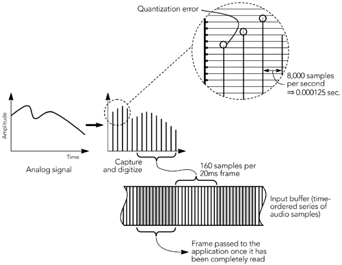
| The media capture process is essentially the same whether audio or video is being transmitted: An uncompressed frame is captured, if necessary it is transformed into a suitable format for compression, and then the encoder is invoked to produce a compressed frame. The compressed frame is then passed to the packetization routine, and one or more RTP packets are generated. Factors specific to audio/video capture are discussed in the next two sections, followed by a description of issues raised by prerecorded content. Audio Capture and CompressionConsidering the specifics of audio capture, Figure 6.1 shows the sampling process on a general-purpose workstation, with sound being captured, digitized, and stored into an audio input buffer. This input buffer is commonly made available to the application after a fixed number of samples have been collected. Most audio capture APIs return data from the input buffer in fixed-duration frames , blocking until sufficient samples have been collected to form a complete frame. This imposes some delay because the first sample in a frame is not made available until the last sample has been collected. If given a choice, applications intended for interactive use should select the buffer size closest to that of the codec frame duration, commonly either 20 milliseconds or 30 milliseconds , to reduce the delay. Figure 6.1. Audio Capture, Digitization, and Framing Uncompressed audio frames can be returned from the capture device with a range of sample types and at one of several sampling rates. Common audio capture devices can return samples with 8-, 16-, or 24-bit resolution, using linear, µ-law or A-law quantization, at rates between 8,000 and 96,000 samples per second, and in mono or stereo. Depending on the capabilities of the capture device and on the media codec, it may be necessary to convert the media to an alternative format before the media can be used ”for example, changing the sample rate or converting from linear to µ-law quantization. Algorithms for audio format conversion are outside the scope of this book, but standard signal-processing texts give a range of possibilities.
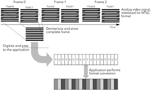
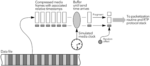
Captured audio frames are passed to the encoder for compression. Depending on the codec, state may be maintained between frames ”the compression context ”that must be made available to the encoder along with each new frame of data. Some codecs, particularly music codecs, base their compression on a series of uncompressed frames and not on uncompressed frames in isolation. In these cases the encoder may need to be passed several frames of audio, or it may buffer frames internally and produce output only after receiving several frames. Some codecs produce fixed-size frames as their output; others produce variable-size frames. Those with variable-size frames commonly select from a fixed set of output rates according to the desired quality or signal content; very few are truly variable-rate. Many speech codecs perform voice activity detection with silence suppression, detecting and suppressing frames that contain only silence or background noise. Suppressed frames either are not transmitted or are replaced with occasional low-rate comfort noise packets. The result can be a significant savings in network capacity, especially if statistical multiplexing is used to make effective use of limited-capacity channels. Video Capture and CompressionVideo capture devices typically operate on complete frames of video, rather than returning individual scan lines or fields of an interlaced image. Many offer the ability to subsample and capture the frame at reduced resolution or to return a subset of the frames. Frames may have a range of sizes, and capture devices may return frames in a variety of formats, color spaces, depths, and subsampling. Depending on the codec used, it may be necessary to convert from the device format before the frame can be used. Algorithms for such conversion are outside the scope of this book, but any standard video signal “processing text will give a range of possibilities, depending on the desired quality and the available resources. The most commonly implemented conversion is probably between RGB and YUV color spaces; in addition, color dithering and subsampling are often required. These conversions are well suited to acceleration in response to the single-instruction, multiple-data (SIMD) instructions present in many processor architectures (for example, Intel MMX instructions, SPARC VIS instructions). Figure 6.2 illustrates the video capture process, with the example of an NTSC signal captured in YUV format being converted into RGB format before use. Figure 6.2. Video Capture Once video frames have been captured, they are buffered before being passed to the encoder for compression. The amount of buffering depends on the compression scheme being used; most video codecs perform interframe compression, in which each frame depends on the surrounding frames. Interframe compression may require the coder to delay compressing a particular frame until the frames on which it depends have been captured. The encoder will maintain state information between frames, and this information must be made available to the encoder along with the video frames. For both audio and video, the capture device may directly produce compressed media, rather than having separate capture and compression stages. This is common on special-purpose hardware, but some workstation audiovisual interfaces also have built-in compression. Capture devices that work in this way simplify RTP implementations because they don't need to include a separate codec, but they may limit the scope of adaptation to clock skew and/or network jitter, as described later in this chapter. No matter what the media type is and how compression is performed, the result of the capture and compression stages is a sequence of compressed frames, each with an associated capture time. These frames are passed to the RTP module, for packetization and transmission, as described in the next section, Generating RTP Packets. Use of Prerecorded ContentWhen streaming from a file of prerecorded and compressed content, media frames are passed to the packetization routines in much the same way as for live content. The RTP specification makes no distinction between live and prerecorded media, and senders generate data packets from compressed frames in the same way, no matter how the frames were generated. In particular, when beginning to stream prerecorded content, the sender must generate a new SSRC and choose random initial values for the RTP timestamp and sequence number. During the streaming process, the sender must be prepared to handle SSRC collisions and should generate and respond to RTCP packets for the stream. Also, if the sender implements a control protocol, such as RTSP, 14 that allows the receiver to pause or seek within the media stream, the sender must keep track of such interactions so that it can insert the correct sequence number and timestamp into RTP data packets (these issues are also discussed in Chapter 4, RTP Data Transfer Protocol). The need to implement RTCP, and to ensure that the sequence number and timestamp are correct, implies that a sender cannot simply store complete RTP packets in a file and stream directly from the file. Instead, as shown in Figure 6.3, frames of media data must be stored and packetized on the fly. Figure 6.3. Use of Prerecorded Content |
EAN: 2147483647
Pages: 108
- Enterprise Application Integration: New Solutions for a Solved Problem or a Challenging Research Field?
- Context Management of ERP Processes in Virtual Communities
- Distributed Data Warehouse for Geo-spatial Services
- Data Mining for Business Process Reengineering
- Relevance and Micro-Relevance for the Professional as Determinants of IT-Diffusion and IT-Use in Healthcare


