9.5 UMTS Architecture Description
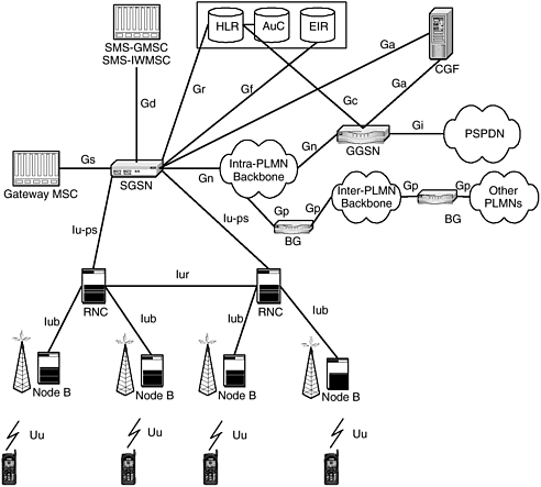
| A UMTS network consists of a radio access network (RAN) that is attached to circuit switched (CS) and packet switched (PS) core networks. In principle, either the CS or PS core network is capable of carrying the subscriber IP traffic. A packet switched core is better suited for the task since it does not reserve transport capacity during the idle periods of the bursty data traffic. The service description of the packet switched core network is specified in 3GPP TS 23.060. The UMTS packet core network adopted many of the GPRS features. The GPRS architecture is described in more detail in Chapter 8, "Data in GPRS Networks." This chapter concentrates on the main differences and the new IP services that the high-capacity WCDMA radio access (UTRAN) enables. The network architecture subchapters describe the PS core, several network access technologies, and IP service networks. The CS domain has been left out from the description since the packet switched core is primarily designed for IP networking. The UMTS network architecture is shown in Figure 9-2. The network architecture in Figure 9-2 depicts the network elements according to the 3GPP Release 99 standard. WCDMA radio interface was the main new item in Release 99. The packet core network elements are the same as in GPRS, but the interfaces differ somewhat. From an IP traffic point of view, the main change is that Iu-ps interface replaces Gb between the core and access networks. IP header compression is required to improve the bandwidth usage over the air interface. In GPRS the compression resides in the SGSN, whereas UMTS moves it into the radio network controller (RNC). Thus the 3G SGSN in the UMTS network does not know anything about the compression or other access-specific low-bandwidth optimizations. The drawback is slightly larger transmission capacity requirement between the 3G SGSN and RNC due to the full IP headers in the packets. Figure 9-2. UMTS network architecture. 3GPP Release 5 and later standards define a new IP multimedia subsystem, IMS. The session initiation protocol that has been specified by the IETF will be used for both subscriber and network internal signaling. The radio network transport will move toward IP from the current ATM infrastructure. The trend toward IP transport is again invisible to the subscriber although it is an important network internal property. Since IP traffic can be carried over any physical transmission medium, the operator has much more freedom in the network implementation. UMTS standards define four different traffic classes: conversational, streaming, interactive, and background. The network implementations map these classes to actual user plane bearers in the radio interface and the transport domain. The standard does not dictate any specific mapping to avoid binding to specific transport technologies. The standard defines a "language" with which the subscribers can request the needed service level, and the network must implement the QoS support consistently over the whole end-to-end user plane path . Thus conversational class traffic makes use of certain queuing priorities in the radio and transport protocols while the other classes utilize some other combination. The radio link setup and PDP context activation specify the exact quality requirements in terms of bit rate, delay, delay variation, and packet loss probability. The admission control in the network may also indicate that the requirements cannot be reached due to network congestion. 3G security architecture follows the GSM architecture in many respects. The trust between the user and home network is based on the subscription and roaming agreement between the home and visited network. A shared secret key between the UMTS subscriber identification module (USIM) and home network is the incarnation of the trust, and the subscriber authentication is based on proving knowledge of this secret key. The authentication procedure also delivers random session keys to cipher and integrity check the traffic between the mobile terminal and radio access network. Roaming and paging in 3G networks are very similar to their GSM counterparts. Handover is more complex due to the soft handover mechanism used. Link-layer protocols in the RNC receive the mobile station's signal from several directions, combine the signals, and forward the result to higher protocol layers . Radio efficiency is significantly improved over the GSM technology, but the RNC has more work in deciding which signals to combine and when to change the active set. 9.5.1 User EquipmentThe user equipment (UE) is the mobile terminal. The UE consists of two parts , the mobile device and the USIM. The mobile device consists of the radio terminal and interfaces (connects) to the network via the Uu interface. Initial mobile terminals will be at least dual mode and able to support both WCDMA/EDGE as well as GSM/GPRS. This is in view of the limited deployment and coverage of WCDMA in the initial phases. The USIM is essentially a smartcard that contains the subscriber's identity, keys used for authentication and encryption, and other subscription information. The USIM also assists in the execution of the authentication algorithm. 9.5.2 UTRAN and GERANAs of Release 5 of UMTS, two types of radio networks now qualify as being UMTS access networks. These are the WCDMA-based UTRAN and the TDMA-based GERAN. UTRAN and GERAN radio network architectures as well as the interfaces are identical. The UTRAN and GERAN networks consist of two distinct elements: Node B, also referred to as the BTS, and the RNC.
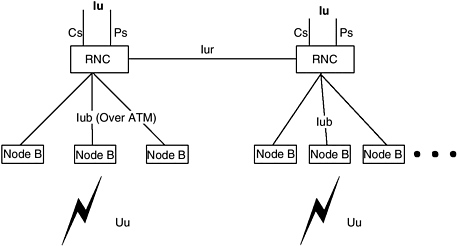
Figure 9-3 shows the UTRAN architecture. Figure 9-3. UTRAN/GERAN architecture. Multiple Node Bs are connected to a single RNC via the Iub interface. The UTRAN can consist of more than one RNC. Inter-RNC communication to enable soft handoffs is accomplished via the Iur interface. RNCs are classified as Serving RNC or Drifting RNC depending on the role played during a mobile-UTRAN connection. An RNC is deemed a RNC (SRNC) if that RNC terminates both the Iu link for the transport of user data as well as the corresponding control signaling to and from the core network. The SRNC is also the one that terminates the radio resource control (RRC) signaling (UE-UTRAN). A mobile station has a maximum of one SRNC at any time. A Drifting RNC (DRNC) is any other RNC in the UTRAN. The DRNC may be involved in performing macro-diversity combining and splitting. The DRNC simply routes the data transparently between the Iub and Iur interfaces. A mobile station may have zero, one, or more DRNCs at any given time. The primary role of Node B is to perform the air interface layer 1 processing functions such as channel coding and interleaving, rate adapatation, spreading, modulation/demodulation, and power control. The node B is the layer 2 bridge when viewed from an IP networking perspective. 9.5.3 Packet Switched Core NetworkUMTS inherits many of the GPRS packet core features and protocols. Chapter 8 describes the baseline GPRS functionality, and this chapter concentrates on the differences in the protocols. The first major difference to GPRS is the air interface capacity allocation. WCDMA allows much higher data rates, up to 2 Mbps. Capacity allocation is also much more flexible than in GSM. The terminal classification to combine PS/CS-capable class A phones and PS only class C phones is similar to GPRS. UMTS implements two-way authentication, which means improved security to the users. Active mobiles perform handovers or cell updates, whereas idle ones without RRC connection only update the registration area (RA). Packet core network functions in the high level are as follows (3GPP TS 23.060 ”GPRS service description):
The network elements that make up the packet switched core are the GGSN, SGSN, and border gateway. UMTS packet data access also supports four different levels of QoS: conversational class, streaming class, interactive class, and background class. Real-time services such as voice, which are sensitive to delay, are assigned conversational class QoS. Audio and video streaming applications are generally assigned streaming class. Conversational and streaming classes are generally treated as real-time connections over the air interface. The interactive class is for applications such as Web browsing and/or gaming. Background class can be assigned to services such as e-mail and file transfer, which can be run in the background while the user is involved in some other active session. The nature of the service and application determines the type of QoS assigned to it. GGSNThe GGSN is the anchor point for a mobile station and can be considered as the default router. The GGSN is selected based on the access point name (APN). When mobile stations request a PDP context to be set up, an APN is included as part of the request. Based on the APN request, the SGSN queries the DNS to determine the GGSN to forward the request to. The DNS response determines the GGSN, and the PDP context is established with that GGSN. The GGSN in UMTS is very much the same as in GPRS networks. A few differences include the existence of an interface called Go between the GGSN and the policy control function (PCF), which is in the IP multimedia subsystem (IMS). The Go interface is a COPS protocol-based interface and is used to specify QoS characteristics for PDP contexts that utilize the IMS. The GGSN in UMTS also supports multiple PDP contexts for a single user as opposed to GPRS, where generally the user has a single PDP context. The GGSN in UMTS is also capable of assigning multiple PDP contexts with a single IP address for the mobile station. This was not possible in GPRS. SGSNThe SGSN in UMTS differs from the SGSN in GPRS networks in terms of the interface that is used to connect to the RNC. The IuPs interface is introduced in UMTS networks, and this is an enhancement over Gb, which is the interface that connects the BSS to the SGSN in GPRS. The IuPs interface is capable of supporting real-time services. Another difference between 2G and 3G SGSN is the compression and ciphering function. 2G SGSN optimizes the radio link usage with TCP/IP header compression. It is also involved in logical link and radio resource management, whereas 3G SGSN is completely free from these radio- related functions. Another difference to note is that two GTP tunnels for carrying user datagrams now exist instead of only one, as was the case with 2.5G GPRS networks. A GTP-U tunnel between the GGSN and the SGSN and another one between the SGSN and the RNC are established for user plane traffic. BORDER GATEWAYThe border gateway is essentially a firewall that protects the packet core from security threats. The GGSN connects to packet data networks such as the Internet via the border gateway. The border gateway network element is the same for both GPRS and UMTS networks. |
EAN: 2147483647
Pages: 164

