6.2 Protocol Architecture
| In this section we will delve into the layers that constitute the protocol stack for CDMA-based wireless data between the MS and the IWF. The initial CDMA-based wireless data deployment was limited to CS data specified in TIA/EIA/IS-99 followed by support for PS data specified in TIA/EIA/IS-657. Subsequently, these standards were combined into one superceding standard specified in TIA/EIA/IS-707. With the introduction of the TIA/EIA/IS-95-B standard, TIA/EIA/IS-707 was enhanced to include high-speed PS data resulting in a new revision, TIA/EIA/IS-707-A. The protocol stack architecture can be divided into three distinct categories:
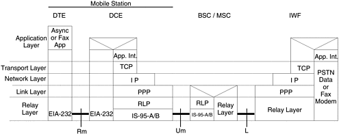
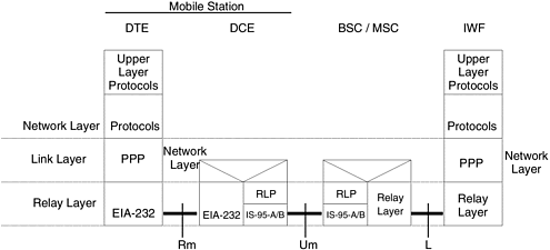
For the most part, analog fax is similar to group-3 digital fax. The essential difference is that in case of analog fax, the Rm interface is replaced by an RJ-11 interface, the DTE is a subscriber fax machine, and an analog fax layer is introduced over the application interface layer. For our purposes it is sufficient to describe the Async data and group-3 fax protocol stack architecture. 6.2.1 Async Data and Fax Protocol Stack ArchitectureThe protocol stack for async data and fax is illustrated in Figure 6-4. Figure 6-4. The async data and group-3 fax protocol stack architecture (circuit switched data). For analog fax, in Figure 6-4, the EIA-232 interface that defines the Rm interface is replaced by an RJ-11 interface and the async or fax layer is replaced by an analog fax layer. APPLICATION LAYERThe application layer consists of an async data or fax user application on a DTE and the associated application layer interfaces on the DCE and the IWF. The application layer interface provides modem control and AT-command processing functionality in addition to negotiation of air interface data compression and actual data compression. Data streams entering from the transport layer are parsed by the application layer interface to extract any option negotiation commands. The local AT commands are processed by the application interface layer, and the remaining data is passed to the Rm interface by the DTE or the PSTN data or fax modem by the IWF. Data streams entering from the Rm interface or the PSTN data or fax modem interface are massaged to insert any in- band commands or option negotiation commands by the MS and the IWF. In addition, the application layer interface at the MS also does the job of extracting and processing any local time-dependent modem control commands. TRANSPORT LAYERThe transport layer provides a reliable delivery service to the upper layers and user data exchanges. It is based on the Transmission Control Protocol (RFC 793) with a few amendments specified by RFC 1122. This error recovery functionality ensures data integrity between the mobile and the IWF required to handle intersystem and hard handovers. NETWORK LAYERThe network layer includes the Internet Protocol (IP), specified in RFC 791, and the Internet Control Message Protocol (ICMP), specified in RFC 792 with a few amendments specified by RFC 1122. A key limitation is that the IP datagrams are not fragmented over the air interface. IP provides global addressability with independence from the type of underlying networks and ICMP control aspects of the IP layers. Upon the establishment of a CS data call, the IWF assigns a temporary IP address to be used by a user session. This IP address is unique to the MS only for the duration of the call. LINK LAYERThe link layer provides an end-to-end link management, multiplexings, and framing service. It consists of the Point-to-Point Protocol (PPP), Link Control Protocol (LCP), and the Internet Protocol Control Protocol (IPCP). The link layer connection state machine consists of two states: closed and open. In the closed state there is no established link layer connection. In the open state there is an established link layer connection. PPP provides framing, CRC checks, and control messaging. LCP provides a mechanism for the MS and the IWF for link establishment and negotiation of various PPP options. IPCP provides a mechanism for negotiating IP addresses and header compression from the IWF at session establishment. The Sub-Network Dependent Convergence Function (SNDCF) does the actual compression of the transport layer and network layer headers. RELAY LAYERThe relay layer spans across the Rm, Um, and L interfaces. It consists of physical and logical channels required to support the upper layers. The relay layer between the DTE and DCE is called the Rm interface and is defined by a simple EIA/TIA-232-E interface (serial link). The relay layer between the MS and BS is called the Um interface and consists of the Radio Link Protocol (RLP) layer and the underlying physical layer that provides the medium for data transmission. It is defined by TIA/EIA/IS-95-A/B standard. The RLP is a nak-based protocol and provides segmentation and reassembly functionality to fit frames transmitted over the air. In addition, the RLP layer improves the error characteristics of the wireless link by providing error detection and packet retransmissions. This reduces the need for transport layer retransmission due to lost data. The relay layer also provides call control, multiplex sublayer, and radio link management functionality. The relay layer between the MSC and the IWF is called the L-interface and uses protocols defined in TIA/EIA/IS-658. It provides a mechanism to transport end-user data between the MS and the IWF via virtual circuits. For CS calls it provides access to the PSTN in order to originate and terminate voice-band modem calls on behalf of modem users. The standard does not describe the PPDN interface to the IWF for PS data services. 6.2.2 Packet-Switched Data Protocol Stack ArchitectureFor the most part the protocol stack is similar to that for CS data. The key difference is the enhancements in the link layer state and the relay layers. The packet data protocol stack is illustrated in Figure 6-5. Figure 6-5. PS data protocol stack architecture (relay layer Rm interface option). NETWORK LAYERUnlike the CS data protocol stack, the support for IP is optional. Alternate network layer protocols are connectionless network protocol (CNLP), specified in ISO-8473, or CDPD, specified in TIA/EIA/IS-732. However, the most common implementation is via IP support. LINK LAYERIn order to support PS data services, the link layer is enhanced to introduce new substates into the connection state machine. The link layer connection can be in one of two primary states: closed and open. The open state is enhanced to include two substates in order to support PS data: active and dormant . The Open link layer connection is in an Active substate when data is being transmitted between the MS and the IWF. In this case, there exists on the IWF an L-interface virtual circuit for the MS and the MS is on a traffic channel with a packet data service option. The Open link layer connection is in a Dormant substate when there is no data being transmitted between the MS and the IWF. In this case, the IWF has no L-interface virtual circuit for the MS and the MS is not on a traffic channel. However, the MS, the BS/MSC, and the IWF maintain link connection state information (PPP session information). While in the Dormant substate, if the IWF or the MS has data to send, then it is not necessary to reestablish any link layer connection (PPP session) or reinitialize any upper-layer protocols. Transition from Dormant to Active state requires simply an establishment of an over-the-air traffic channel between the MS and the BS/MSC. RELAY LAYERAs in the case of CS data, the relay layer spans across the Rm, Um, and L interfaces. For the Um interface, the relay layer for PS data consists of the Radio Link Protocol (RLP) layer and the underlying physical layer that provides the medium for data transmission. Low-speed PS data support (up to 14.4 Kbps) is provided by introducing a call control state machine for the radio link in the MS and the BS/MSC. However, no enhancements to the physical layer are required. With the advent of higher-speed data support in competing technologies such as GPRS, the EIA/TIA/IS-95-B standard was introduced, which enhanced the relay layer at the Um interface to provide high-speed data support. A new type of physical traffic channel, called the supplemental code channel, was introduced and had the same characteristics of the original TIA/EIA/IS-95-A traffic channel, now referred to as the fundamental channel. The RLP layer was enhanced to provide allocation and deallocation of this new type of channel and to provide multiplexing of data and control frames between the fundamental and supplemental code channels. |
EAN: 2147483647
Pages: 164

