4.4 High-Speed Circuit Switched Data
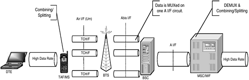
| The HSCSD feature allows subscribers to access higher data rates with multiple TCH/Fs (Figure 4-16). HSCSD has defined mechanisms to make efficient and flexible use of radio resources for HSCSD. Combining/splitting functionality is defined in the IWF and terminal to separate a data stream into n TCH/F, where n ranges from 1 to 8. These n TCH/Fs, carrying a data stream, are referred to as HSCSD channels. The HSCSD channels carry the substreams as if they were independent of each other. However, the HSCSD channels, serving one stream, are controlled as one radio link. Any cellular operation (e.g., handover), treats the HSCSD channels of one stream as a single entity. Figure 4-16. Network architecture for supporting HSCSD. Before HSCSD, the air interface user rate in the original GSM data transmission was limited to 9.6 Kbps. The HSCSD made it possible to have user data rates up to 57.6 Kbps, with the same GSM RF equipment. The data rate is limited by the per-channel capacity on the A interface, which is 64 Kbps. To carry more than 64 Kbps, another split/combine function has to be defined and implemented for the terrestrial circuits on the terminating party. This is not realistic and not needed for circuit switched data. HSCSD doesn't impose any new requirement for the interconnection with PSTN, ISDN, CSPDN, and PSPDN. The subscriber uses general bearer services as defined in GSM TS 02 series, and the HLR stores the bearer capability information as part of the service profile. HSCSD serves both transparent and nontransparent connections. In transparent data transmission, the data frames on the HSCSD channels carry data substream numbers to retain the order of transmission between the split/combine functions. Between these functions, channel internal multiframing is also used in order to increase the tolerance against inter-channel transmission delays. A transparent connection may request a data rate that is not a multiple of rates provided by one TCH/F. In such a case the data bits in the n th TCH/F need to be padded with fill bits. In nontransparent connection, the RLP and L2R are modified to support multiple parallel TCH/Fs instead of only one TCH/F. Also, the RLP frame sequence number range is increased to accommodate the enlarged data transmission rate. HSCSD provides both symmetric and asymmetric connection setup. In the symmetric connections, the number of HSCSD channels is same in both uplink and downlink directions. In asymmetric connections, the number of HSCSD channels is different. The network usually allocates asymmetric connections when the desired air interface user rate requirement cannot be met using a symmetric configuration. The network in this case gives priority to fulfilling the air interface user rate requirement in the downlink direction. This is in consideration that the downlink bandwidth is needed more than the uplink bandwidth for most data applications. Note that the asymmetric connections are only given for nontransparent HSCSD. 4.4.1 HSCSD Call SetupAt call setup, an HSCSD user sends a set of parameters to the network indicating the desired HSCSD characteristics (e.g., number of TCH/Fs). In the case of nontransparent HSCSD connections, the user may also request user initiated service level upgrading and downgrading during the call. The MSC requests the BSC to allocate the channel configuration using parameters derived from the HSCSD- related parameters agreed on in the setup phase. Based on these parameters and operator preferences, the BSC then allocates a suitable number of channels and a suitable channel coding for the connection. Separate channel activation is applied for each of the HSCSD channels. At assignment completion, the BSS informs the MSC of the chosen HSCSD configuration and the MSC may seize the interworking resources accordingly . The network responds with a set of parameters, indicating the configuration it has prepared to give to the mobile station. 4.4.2 Resource Upgrading, Downgrading, and Configuration ChangeResource upgrading means allocating more channels to the HSCSD configuration. On the contrary, in resource downgrading channels are released. The network or the MS can initiate these procedures. At resource modification completion, the BSC signals to the MSC the new HSCSD configuration, and the MSC may adjust the interworking resources accordingly. These procedures can be applied on both transparent and nontransparent connections. For the transparent connection, the alteration is not allowed to change the air interface user rate, and the alteration is not allowed by a user-initiated procedure. 4.4.3 Air Interface for HSCSDThe number of HSCSD channels used for a session influences the design of a mobile station. Before HSCSD, a GSM phone had a gap of three time slots between transmit and receive channels. Considering that the total number of channels on a carrier is eight, an MS cannot use more than five channels while tuned to one carrier frequency. Therefore, another class of mobile is defined that has RF equipment to do simultaneous receive and transmit. This class of phones is named HSCSD class 2, while the former is HSCSD class 1. The class 2 phones covers from 6 to a maximum of 16 channels, with 8 channels in each direction. For HSCSD, the channels can be allocated from consecutive or nonconsecutive time slots. Let's see how the TCH/F and the associated signaling channels are used for HSCSD. GSM has defined FACCH and SACCH as the associated signaling channels with a TCH/F. The FACCH carries the signaling messages that cannot be delayed (e.g., handover messages). With multiple TCH/Fs, HCSD designates one bidirectional TCH/F as the main channel. The FACCH of the main channel is used for all fast signaling related to a data session, and the SACCHs of all TCH/Fs are used individually. The same frequency hopping sequence and training sequence is used for all the channels in an HSCSD configuration. The same channel coding is used for all the channels in an HSCSD configuration. Each of the HSCSD channels is ciphered using separate ciphering keys, but they all are derived from the same subscriber ciphering key (Kc). |
EAN: 2147483647
Pages: 164