4.2 Traffic Channel Data Services
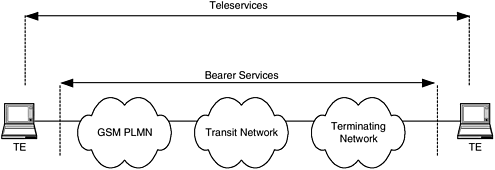
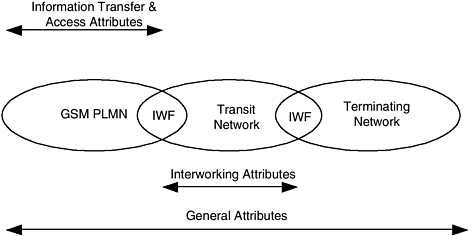
| The basic idea in providing TCH data service is to provide a CS conduit for carrying data from the user through the GSM PLMN and vice versa. The conduits are composed of CS bearers in the network and the TCH over the air interface. The data path establishment procedure is very similar to the voice path establishment. There is also an IWF with the MSC, which serves as a gateway between data signals in the GSM PLMN and other networks, such as PSTN (public switched telephone network) and PSPDN (public switched packet data network). With a TCH-Full rate (TCH/F), the maximum effective data rate possible is 9.6 Kbps. With a TCH-Half rate (TCH/H), the maximum data rate is 4.8 Kbps. The GSM PLMN also provides high-speed circuit switched data (HSCSD), which combines multiple TCH/Fs and can provide a maximum data rate of 56 Kbps. GSM provides transparent and nontransparent connection for the TCH data services. In the transparent connection, the data services see the path between the IWF and terminal as a constant rate conduit. The GSM PLMN doesn't intercept the data protocol and the data traffic. The radio interface doesn't do any extra processing to safeguard the data from errors. The transparent connection is usually suited for constant rate and fixed delay applications. In the nontransparent connection, the data protocol and the traffic are intercepted in the GSM PLMN. The data are intercepted to provide reliable transport over the low-bandwidth and error-prone radio link. The GSM specifications have defined link-layer protocols, L2R and RLP, for this purpose. Example applications for nontransparent connections are X.25 LAP-B and character-mode protocols like X.28. For carrying data through a GSM PLMN, a set of services is defined. These services, called bearer services and teleservices , allow different types of data applications to carry data through the GSM PLMN. We will discuss these services in the next section. The GSM PLMN also interconnects with ISDN, CSPDN, and PSPDN for transparent/nontransparent data services using an IWF. The GSM PLMN performs a set of functions so the data can be carried between the IWF and mobile terminal. These functions are mainly to adapt the data to the circuit switch nature of the transport and the radio nature of the air interface. In this section we will also review those functions. 4.2.1 GSM Bearer Services and TeleservicesA bearer service is subscribed to individually by a GSM subscriber. It is stored as part of the subscriber profile in the HLR/VLR. The GSM PLMN uses the bearer services to provision the capability of transmission of data between two access points (Figure 4-2). It is a network transmission property and is not visible to the end terminal. The service, that is visible to the terminal is called teleservices. The teleservices are complete end-to-end services, including terminal capabilities. For example, Teletex is a teleservice , and a subscriber can use data, circuit duplex, and synchronous as bearer services to carry Teletex through the PLMN. Some teleservices may not have a bearer service (e.g., SMS). This is because there is no need to establish bearers for this service. The GSM bearer services are defined in GSM TS 02.02. The GSM teleservices are defined in GSM TS 02.03. A user can only subscribe to a bearer service and use it for a data application (e.g., IP). In this case, the data application is transparent to the GSM PLMN. Figure 4-2. Bearer services and teleservices supported by a GSM PLMN. Some examples of teleservices are telephony and emergency call. As the teleservices are subscriber visible and commonly understood , we do not discuss them in detail. Readers can refer to GSM TS 02.03 for further details. Bearer services are described by a set of attributes. These attributes are described in detail in GSM 02.01. In this book we will try to give a concept of bearer services by discussing a few of the important attributes. An example of a bearer attribute is symmetry; a possible value of symmetry is bidirectional symmetrical transmission. This attribute is mentioned by the user when the same transmission capability is desired in both uplink and downlink directions. In general, the bearer services attributes can be grouped into four categories:
Figure 4-3 shows the field of applicability of the preceding attribute categories. Figure 4-3. Applicability of bearer services categories. The bearer service category that we use frequently in this chapter is the information transfer category. The following are the bearer services under this category.
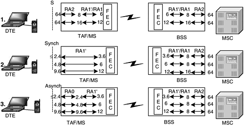
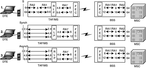
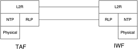
4.2.2 Rate Adaptation FunctionIn the GSM PLMN, data traffic goes through different interfaces, and these interfaces support different data rates. For example, air interface supports up to 12.0 Kbps, and A interface supports up to 64 Kbps. Rate adaptation (RA) provides data transmission speed adaptation for different interfaces. For instance, if we hook up a terminal that sends data at 64 Kbps, then for the air interface the RA function will down-convert the data rate to 12 Kbps. For the A interface, the RA function will up-convert the data to 64 Kbps. The GSM specifications have adapted the RA function from ITU-T V.110, and the details can be found in GSM TS 04.21. The RA functions are described next. RA0 RA0 is used for converting incoming asynchronous data from the TE to synchronous data and vice versa. The synchronous transmission is needed because of the circuit switch nature of the air interface and the PLMN. The asynchronous data is padded to fit the same or next higher synchronous rate. The nearest higher synchronous rate is defined by 2 to the power n (where n RA1RA1 is the intermediate rate adaptation function, which turns either the output of the RA0 function or a synchronous user data stream into a data stream at 8, 16, or 32 Kbit/s by bit repetition and frame addition. The resulting data frames also contain control and frame synchronization bits. RA2RA2 converts intermediate rates of 8 and 16 Kbps to 64 Kbit/s. This is the final conversion rate. The resulting data can be carried to the terminal equipment or to the A interface. RA2 is usually performed by multiplexing several 8 or 16 Kbps streams. RA1' RA1' transforms data rates from the synchronous user data stream or the output of the RA0 to rates supported on the air interface while adding some control bits. The synchronous data rates of Figure 4-4 illustrates how the different rate adaptations work together for carrying data traffic. Figure 4-4. RA examples for transparent data. Reprinted with permission from GSM and Personal Communications Handbook , by Redl, Weber, and Oliphant. Norwood, MA: Artech House Publishing, 1998. (www.artechhouse.com) Figure 4-4 shows the rate adaptation for some transparent data connections. The first case is a DTE supporting the ISDN S interface. The mobile terminal will first apply RA2 to reduce the data rate from 64 to 8 or 16 Kbps, and then apply RA1/RA1' to reduce the data rate to 6/12. The BSS performs the reverse change, so the user data rate can come back to 64 Kbps for A-interface transmission. In the second case, a synchronous DTE is rate adapted with RA1' to 3.6, 6, or 12 Kbps. The BSS applies the RA1'/RA1 function to transform the data to the intermediate rate of 8 or 16 Kbps. The RA2 function is used to adapt the data rate for the A interface. The third case of asynchronous DTE is very similar to the second case, except that the RA0 is used to convert asynchronous transmission to synchronous transmission. Nontransparent data makes use of the RLP function (Figure 4-5). For the first case, RA2 is used to reduce the data rate to 8 or 16 Kbps, and then RA1 is used to reduce the rate to 4.8 or 9.6 Kbps. The choice between 4.8 Kbps or 9.6 Kbps depends on the channel rate that is to be used, which in turn is set by the bearer service. The RLP always uses the highest available rate. For TCH/H the data will be downconverted to 4.8 Kbps, and for TCH/F the data will be downconverted to 9.6 Kbps. The output of RLP is adapted to the data rates available at the air interface (i.e., 6 or 12 Kbps). For the second and third case (i.e., synchronous and nonsynchronous transmission), the rate adaptations chosen at different points are the same. This is because the RLP doesn't distinguish between synchronous and asynchronous transmission. It uses its own mechanism to deliver data to its peer entity at the IWF. Figure 4-5. RA examples for nontransparent data. Reprinted with permission from GSM and Personal Communication Handbook , by Redl, Weber, and Oliphant. Norwood, MA: Artech House Publishing, 1998. (www.artechhouse.com) 4.2.3 Layer 2 Relay ProtocolThe Layer 2 Relay (L2R) protocol acts as a relay between the user nontransparent protocol (NTP) and the GSM-defined RLP. It provides a reliable transportation of user protocols across the GSM radio interface. The L2R uses the services provided by the RLP to transport the protocol information between the MS and the IWF. It also specifies protocol conversion between the user data structure (e.g., ITU-T defined X.25 Layer 2 frames) and a structure more adapted for the RLP. The L2R functions are located in the TAF and the IWF. Only nontransparent protocols can utilize L2R, because the GSM PLMN does not intercept transparent protocols. The L2R is comprised of three functional entities: an NTP entity, an L2R protocol entity, and a relay entity (Figure 4-6). The NTP entity interfaces the L2R to the physical layer and provides an interface to the particular NTP. The L2RP entity interfaces the L2R to the RLP entity and provides an interface to the appropriate L2R protocol. The relay entity provides the mapping between the NTP entity and the L2R entity. Figure 4-6. L2R protocol model. The GSM standards have specified L2R for two protocols. It has specified L2RBOP for the ITU-T X.25 protocol, which is used for LAPB and for the nontransparent fax. GSM has specified L2RCOP for ITU-T X.28, which is also known as the start/stop protocol. The protocols are very similar, and we give an overview of both. L2RBOPFor L2RBOP, the NTP entity (Figure 4-6) is called LAPB entity and it terminates the LAPB protocol from terminal or network. The relay entity is called BORE, and it provides the mapping of services between L2RBOP and LAPB. The L2RP entity is called L2RBOP, and it provides the interface to the RLP. The L2RBOP entity segments and reassembles the LAPB user information fields to fit into service data units (SDUs) of RLP. These segments are transferred between L2Rs in n octet protocol data units (PDUs). The number n depends on the negotiated RLP version and RLP frame size. The L2RBOP also provides facilities for transferring LAPB connection control information between L2Rs. The LAPB connection control information allows LAPB connections to be established, reset, and released. It also provides a flow control and a mechanism to transfer flow control information between L2Rs. L2RCOPThis section describes the L2R functionality for nontransparent character-oriented protocols (e.g., ITU-T X.28). In the context of Figure 4-6, the NTP entity for L2RCOP is called character-oriented nontransparent protocol (CONT), the relay entity is character-oriented relay entity (CORE), and the L2RP is L2R character-oriented protocol. The X.28 information is transferred between L2Rs in fixed-length n octet protocol data units (PDUs). The CORE relays status changes, break conditions, and characters in both directions between the CONTP (X.28) entity and the L2RCOP entity. The L2RCOP entity performs functions similar in scope to L2RBOP. It provides radio link connection control to establish and release the connection to its peer L2RCOP entity. It also provides assemble and disassemble for data transfer. Data characters are assembled into L2RCOP PDUs until either the PDU is full or the radio link can accept another service data unit. The L2RCOP entity transfers interface status information between L2Rs using the status octets in L2RCOP PDUs. It also provides a flow control and a mechanism to transfer flow control information between the L2Rs. 4.2.4 Radio Link ProtocolThe radio link protocol (RLP) provides error control and retransmission mechanisms to increase the chance of delivering data over the air interface. RLP is implemented on TAF and IWF. It is based on layer 2 LAPB and is used by nontransparent data services. An RLP frame (Figure 4-7) has three main fields: header, information (payload), and frame check sequence (FCS). The header carries the control information to establish or release an RLP link, a sequence number for the insequence delivery of the frames, and so on. The information field carries the user data from the NTP. The FCS is used to detect transmission errors in an RLP frame. The GSM TS 04.22 specifies a polynomial, which combines the header and information bits to generate FCS. Based on FCS, the receiving RLP accepts or rejects a frame. In case of frame rejection , the sending entity retransmits the frame. This is also referred to as the automatic repeat request (ARQ) mechanism. We will not go into details of control commands and frame types; they can be found in GSM TS 04.22. RLP frames are sent in strict alignment with the radio transmission. An RLP frame has a fixed length of 240 bits, used when the channel coding is TCH/F4.8 or TCH/F9.6. Figure 4-7. RLP frame structure for TCH/F4.8 or TCH/F9.6. Either a terminal or IWF can initiate an RLP link. GSM specifications provide procedural means to deal with contentious situations, should they ever occur. RLP allows simultaneous information transfer in both directions. GSM specifications do not define the transfer of RLP states in handoff. Therefore, inter-MSC/IWF handoff results in RLP reset and may cause data loss. There are three versions of RLP based on the number and type of supported radio links. The RLP version 0 uses one physical link (i.e., one TCH). The RLP version 1 also uses one physical link but also supports data compression. The only defined data compression is V.42bis and is used to compress payload of the data packets. The RLP version 2 is designed to support multiple physical links, up to eight. An example application of RLP version 2 is HSCSD. The RLP has two modes of transmission: asynchronous balanced mode (ABM) and asynchronous disconnected mode (ADM). The ABM is the data link operational mode. In this mode, either RLP entity may send commands at any time and may initiate response frame transmission without receiving explicit permission to do so from the other RLP station. In ADM, an RLP entity is disconnected from the data link and cannot transmit/receive data. 4.2.5 Packet Network AccessA GSM data terminal, in most cases, needs to have a data session with a terminal in another packet network. For this purpose, the GSM PLMN provides access to other packet networks, such as CSPDN, PSPDN, and ISDN. The GSM PLMN is a different network from these packet networks, and for communication with them an IWF is required. The GSM has specified the following access cases:
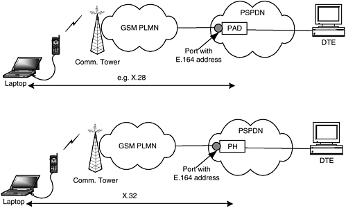
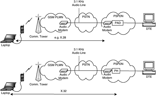
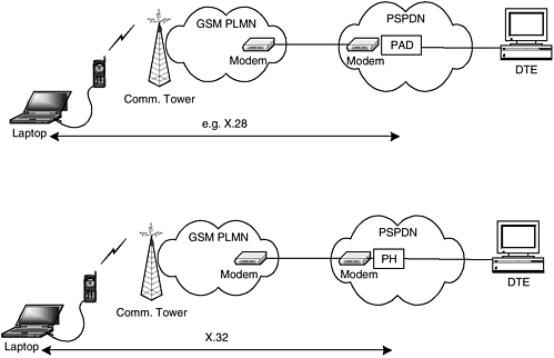
GSM PLMN TO PSPDNPSPDN is a packet-based network such as public Internet or X.25-based networks. The GSM specifications define access to a PSPDN in GSM TS 09.05. The access is possible either through a packet assembler disassembler (PAD) or a packet handler (PH). The PAD is a protocol converter interfacing asynchronous terminals with a PSPDN. The PAD access is for those terminals that do not support a packet protocol and is only supported in the mobile origination direction. The PAD takes the ASCII streams coming from the terminals and converts them into PSPDN protocols (e.g., IP or ITU-T X.25). ITU-T X.28 defines the control procedures to establish the connections to the PAD and could be used for establishing an asynchronous connection. On the other hand, the PH is accessed by a terminal that has a packet protocol such as ITU-T X.32. The advantage in the PH access is that both mobile originated and terminated data calls are possible. GSM defines two types of accesses for both PAD and PH, which are basic access and dedicated access. It is a network operators option to provide either or both of these accesses .
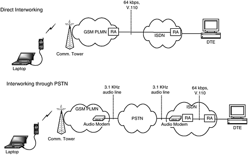
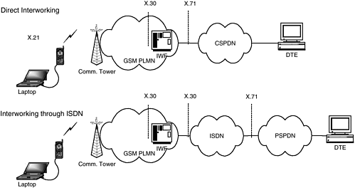
GSM PLMN TO ISDNThe interworking of GSM and ISDN is specified in GSM TS 09.03 (Figure 4-11). The maximum data rate in GSM is 9.6 Kbps, and the minimum data rate in ISDN is 64 Kbps. This mismatch results in inefficient use of digital lines. Therefore, in practice it may not be a commonly used interworking. An ISDN network can be connected directly or indirectly through a PSTN network. Figure 4-11. Interworking between ISDN and GSM PLMN. In the direct approach, the GSM PLMN can be interconnected directly via a rate adapter to the ISDN network via a dedicated line. The subscriber subscribes to a UDI bearer service. In an indirect approach, the GSM PLMN is connected to the ISDN network via a PSTN network. From the GSM PLMN point of view, the connection to the ISDN network is a PSTN network connection with audio modem. The ISDN network needs to have interworking with the PSTN network, which is comprised of audio modem and rate adapter. ACCESS TO CSPDNCircuit switched public data networks (CSPDNs) are general-purpose data networks. Like GSM PLMN, they use circuit switched transmission for transporting data. Interworking between GSM PLMN and CSPDN is defined in GSM TS 09.04 (Figure 4-12). The GSM PLMN provides only synchronous data interworking at the rates of 2.4, 4.8, and 9.6 Kbps. Also, it interworks only transparent data services, since it is not possible to flow control the terminals connected to a CS packet network. There are two ways to interwork with the CSPDN: directly or via the ISDN. In direct interworking, ITU-T defined X.21 is used as a user-network interface. In indirect interworking via ISDN, the user-network interface is according to the ISDN standards, which are defined in GSM TS 09.07. Figure 4-12. Interworking between CSPDN and GSM PLMN. The PLMN is connected to a CSPDN using an IWF according to ITU-T X.300. The interface between the IWF and CSPDN is in accordance with ITU-T X.71 (direct interworking). In GSM, SS7 is used for signaling; therefore, an interworking needs to be defined between X.71 and SS7. If the PLMN is connected to CSPDN via ISDN, the interface to ISDN shall be according to GSM 09.07 and the information rate adaptation is according to ITU-T X.30. End-to-end transmission is circuit based. Before exposing the air interface to the transmission of user data, an end-to-end terminal synchronization needs to be established. For this purpose, the IWF will send synchronization frames to the mobile terminal. On recognizing frame alignment, the IWF will stop sending the synchronization frames and connect the CSPDN to the terminal. |
EAN: 2147483647
Pages: 164
- Chapter III Two Models of Online Patronage: Why Do Consumers Shop on the Internet?
- Chapter V Consumer Complaint Behavior in the Online Environment
- Chapter X Converting Browsers to Buyers: Key Considerations in Designing Business-to-Consumer Web Sites
- Chapter XI User Satisfaction with Web Portals: An Empirical Study
- Chapter XII Web Design and E-Commerce
 6) times 600 bit/s.