12-1 network ip-address wild-card-mask area area-id
| < Free Open Study > |
12-1 network ip-address wild-card-mask area area-idSyntax Description:
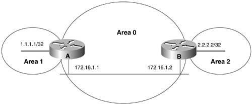
Purpose: The network command is used to define the interfaces that will run OSPF and the OSPF area of the interface. One or more interfaces can be selected with a single network command. If the IP address assigned to an interface is part of the address block the ip-address/wild-card-mask pair defines, the interface will be enabled for OSPF in the indicated area. Initial Cisco IOS Software Release: 10.0 Configuration Example 1: Using a Host Address to Enable OSPF on an InterfaceIn Figure 12-1, host addresses are initially used to configure the interfaces to run OSPF. A host address consists of an IP address and a 32-bit mask in the form Figure 12-1. Network Used to Illustrate the Use of the OSPF network Command
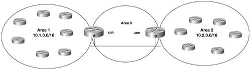
This address/mask pair defines an IP address block that contains one address. Therefore, this form can be used to enable only one interface per network statement for OSPF. Router A interface Loopback0 ip address 1.1.1.1 255.255.255.255 ! interface Ethernet0/0 ip address 172.16.1.1 255.255.255.0 ! router ospf 1 network 1.1.1.1 0.0.0.0 area 1 network 172.16.1.1 0.0.0.0 area 0 ________________________________________________________________ Router B interface Loopback0 ip address 2.2.2.2 255.255.255.255 ! interface Ethernet0 ip address 172.16.1.2 255.255.255.0 ! router ospf 1 network 2.2.2.2 0.0.0.0 area 2 network 172.16.1.2 0.0.0.0 area 0 VerificationVerify that the proper interfaces have been configured for OSPF. rtrA# show ip ospf interface Ethernet0/0 is up, line protocol is up Internet Address 172.16.1.1/24, Area 0 Process ID 1, Router ID 1.1.1.1, Network Type BROADCAST, Cost: 10 Transmit Delay is 1 sec, State DR, Priority 1 Designated Router (ID) 1.1.1.1, Interface address 172.16.1.1 Backup Designated router (ID) 2.2.2.2, Interface address 172.16.1.2 Timer intervals configured, Hello 10, Dead 40, Wait 40, Retransmit 5 Hello due in 00:00:02 Index 1/2, flood queue length 0 Next 0x0(0)/0x0(0) Last flood scan length is 2, maximum is 2 Last flood scan time is 0 msec, maximum is 0 msec Neighbor Count is 1, Adjacent neighbor count is 1 Adjacent with neighbor 2.2.2.2 (Backup Designated Router) Suppress hello for 0 neighbor(s) Loopback0 is up, line protocol is up Internet Address 1.1.1.1/32, Area 1 Process ID 1, Router ID 1.1.1.1, Network Type LOOPBACK, Cost: 1 Loopback interface is treated as a stub Host ________________________________________________________________ rtrB# show ip ospf interface Ethernet0 is up, line protocol is up Internet Address 172.16.1.2/24, Area 0 Process ID 1, Router ID 2.2.2.2, Network Type BROADCAST, Cost: 10 Transmit Delay is 1 sec, State BDR, Priority 1 Designated Router (ID) 1.1.1.1, Interface address 172.16.1.1 Backup Designated router (ID) 2.2.2.2, Interface address 172.16.1.2 Timer intervals configured, Hello 10, Dead 40, Wait 40, Retransmit 5 Hello due in 00:00:00 Neighbor Count is 1, Adjacent neighbor count is 1 Adjacent with neighbor 1.1.1.1 (Designated Router) Suppress hello for 0 neighbor(s) Loopback0 is up, line protocol is up Internet Address 2.2.2.2/32, Area 2 Process ID 1, Router ID 2.2.2.2, Network Type LOOPBACK, Cost: 1 Loopback interface is treated as a stub Host Configuration Example 2: Using the Same Network/Mask Pair in the OSPF network Statement That Is Used for the InterfaceOne problem that can arise when using a host address in the network statement is if the IP address of the interface changes. If you change the IP address of the Ethernet interface on Router A from 172.16.1.1 to 172.16.1.3, then the interface will no longer be enabled for OSPF. You need to delete the network statement containing the host route 172.16.1.1 and re-enter the network statement using the host route 172.16.1.3. If you change the IP address on the Ethernet interface on Router A, you should see the following output: rtrA# conf t Enter configuration commands, one per line. End with CNTL/Z. rtrA(config)# int e0/0 rtrA(config-if)# ip add 172.16.1.3 255.255.255.0 rtrA(config-if)# ^Z rtrA# 05:23:52: %OSPF-5-ADJCHG: Process 1, Nbr 2.2.2.2 on Ethernet0/0 from FULL to DOW N, Neighbor Down: Interface down or detached You have broken the OSPF network and Routers A and B are no longer talking to OSPF. If you had used the same address (almost) and mask (reverse) that was assigned to the interface in the network command then this problem would have gone away. Router A router ospf 1 network 1.1.1.1 0.0.0.0 area 1 network 172.16.1.1 0.0.0.255 area 0 The new address/mask pair defines the IP address block 172.16.1.0 “172.16.1.255. If any IP address in this range is used, the Ethernet interface will still be activated for OSPF. VerificationVerify that OSPF is active on the Ethernet interface on Router A. rtrA# show ip ospf interface ethernet 0/0 Ethernet0/0 is up, line protocol is up Internet Address 172.16.1.1/24, Area 0 Process ID 1, Router ID 1.1.1.1, Network Type BROADCAST, Cost: 10 Transmit Delay is 1 sec, State WAITING, Priority 1 No designated router on this network No backup designated router on this network Timer intervals configured, Hello 10, Dead 40, Wait 40, Retransmit 5 Hello due in 00:00:04 Wait time before Designated router selection 00:00:34 Index 1/2, flood queue length 0 Next 0x0(0)/0x0(0) Last flood scan length is 1, maximum is 2 Last flood scan time is 0 msec, maximum is 0 msec Neighbor Count is 0, Adjacent neighbor count is 0 Suppress hello for 0 neighbor(s) Changing the IP address on an active OSPF interface will cause OSPF to go inactive on the interface until the router determines that the new IP address falls within the range of one of the network commands. If it does, OSPF will be reactivated on the interface. Configuration Example 3: Using a Shorter Mask to Enable OSPF on Multiple InterfacesIn Figure 12-2, the routers in Area 1 use IP addresses assigned from the IP address block 10.1.0.0/16, and the routers in Area 2 use the address block 10.2.0.0/16. For this case, only one network statement is needed on the routers in Areas 1 and 2 and two network statements are needed on the Area Border Routers (ABRs). Assume there are 20 routers in Area 1 and each router has five interfaces. If we use the methods from configuration example 1 or 2, we would need to configure five network statements per router. If an interface is added to a router, then a new OSPF network statement needs to be configured on that router. This would work well, but it could become administratively intensive . If one network statement is used, then no additional OSPF configuration would be necessary when a new interface is added to a router. The configurations for the routers are shown in the listing that follows the figure. Figure 12-2. If All Interfaces on a Router Have Been Assigned to a Common IP Address Block and OSPF Area, Then One network Statement Can Be Used To Enable the Interfaces for OSPF Router A router ospf 1 network 172.16.1.0 0.0.0.255 area 0 network 10.1.0.0 0.0.255.255 area 1 ________________________________________________________________ Router B router ospf 1 network 172.16.1.0 0.0.0.255 area 0 network 10.2.0.0 0.0.255.255 area 2 ________________________________________________________________ Area 1 Router router ospf 1 network 10.1.0.0 0.0.255.255 area 1 ________________________________________________________________ Area 2 Router router ospf 1 network 10.2.0.0 0.0.255.255 area 2 Troubleshooting
|
| < Free Open Study > |
EAN: 2147483647
Pages: 236