11-1 neighbor ip-address
| < Free Open Study > |
11-1 neighbor ip-addressSyntax Description:
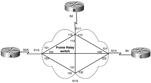
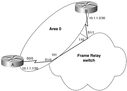
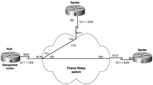
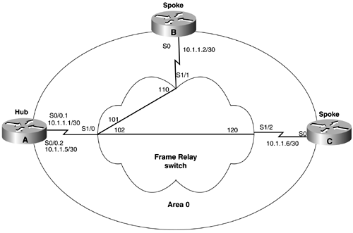
Purpose: To configure OSPF neighbors over a nonbroadcast multiaccess (NBMA) network such as Frame Relay or X.25. Initial Cisco IOS Software Release: 10.0 (12.0 for multipoint networks) Configuration Example 1: Using the neighbor Command to Enable OSPF on an NBMAOSPF treats an NBMA network like any other broadcast network such as Ethernet. Because of this, OSPF thinks the network has broadcast capabilities even though it does not. This lack of a broadcast capability necessitates the use of the neighbor command to establish an OSPF neighbor. Prior to the introduction of the ip ospf network interface commands (see Sections 19-11 through 19-14) the neighbor command was used to configure OSPF neighbors over NBMA networks such as X.25 and Frame Relay. The ip ospf network interface commands have removed the necessity of using the neighbor command, but an understanding of the use of the neighbor command will reinforce the concepts covered in Sections 19-11 through 19-14. Figure 11-1 shows the topology that is used in this chapter to demonstrate the use of the OSPF neighbor command. A Cisco router has been configured as a Frame Relay switch in order to demonstrate the behavior of OSPF over an NBMA network. The configuration for the Frame Relay switch is shown in the listing that follows the figure. The four interfaces on the Frame Relay switch are fully meshed with the DLCIs shown in Figure 11-1. Figure 11-1. Fully Meshed Frame Relay Switch Used to Demonstrate the Use of the OSPF neighbor Command Frame Switch hostname frame-relay ! frame-relay switching ! interface Serial1/0 no ip address no ip directed-broadcast encapsulation frame-relay no ip mroute-cache no fair-queue clockrate 2015232 frame-relay lmi-type ansi frame-relay intf-type dce frame-relay route 101 interface Serial1/1 110 frame-relay route 102 interface Serial1/2 120 frame-relay route 103 interface Serial1/3 130 ! interface Serial1/1 no ip address no ip directed-broadcast encapsulation frame-relay clockrate 2015232 frame-relay lmi-type ansi frame-relay intf-type dce frame-relay route 110 interface Serial1/0 101 frame-relay route 112 interface Serial1/2 121 frame-relay route 113 interface Serial1/3 131 ! interface Serial1/2 no ip address no ip directed-broadcast encapsulation frame-relay clockrate 2015232 frame-relay lmi-type ansi frame-relay intf-type dce frame-relay route 120 interface Serial1/0 102 frame-relay route 121 interface Serial1/1 112 frame-relay route 123 interface Serial1/3 132 ! interface Serial1/3 no ip address no ip directed-broadcast encapsulation frame-relay clockrate 2015232 frame-relay lmi-type ansi frame-relay intf-type dce frame-relay route 130 interface Serial1/0 103 frame-relay route 131 interface Serial1/1 113 frame-relay route 132 interface Serial1/2 123 For the first configuration example, an OSPF neighbor relationship will be established over Frame Relay between two OSPF routers as shown in Figure 11-2. The initial configurations for Routers A and B are shown in the listing that follows. The routers will learn the local DLCI numbers through inverse ARP so the DLCIs do not need to be explicitly configured. Figure 11-2. If the ip ospf network Command Is Not Used on an NBMA Network, then the OSPF neighbor Command Must Be Configured on One End of the Frame Relay Link Router A interface Loopback0 ip address 1.1.1.1 255.255.255.255 ! interface Serial0/0 ip address 10.1.1.1 255.255.255.252 encapsulation frame-relay frame-relay lmi-type ansi ! router ospf 1 network 10.1.1.0 0.0.0.3 area 0 ________________________________________________________________ Router B interface Loopback0 ip address 2.2.2.2 255.255.255.255 ! interface Serial0 ip address 10.1.1.2 255.255.255.252 encapsulation frame-relay frame-relay lmi-type ansi ! router ospf 1 network 10.1.1.0 0.0.0.3 area 0 Verify that Routers A and B have IP connectivity by using the ping command. rtrA# ping 10.1.1.2 Type escape sequence to abort. Sending 5, 100-byte ICMP Echos to 10.1.1.2, timeout is 2 seconds: !!!!! Success rate is 100 percent (5/5), round-trip min/avg/max = 4/4/8 ms List the Frame Relay DLCIs that the routers are using. rtrB# show frame-relay map Serial0 (up): ip 0.0.0.0 dlci 113(0x71,0x1C10) broadcast, CISCO, status defined, inactive Serial0 (up): ip 0.0.0.0 dlci 112(0x70,0x1C00) broadcast, CISCO, status defined, inactive Serial0 (up): ip 0.0.0.0 dlci 110(0x6E,0x18E0) broadcast, CISCO, status defined, active Serial0 (up): ip 10.1.1.1 dlci 110(0x6E,0x18E0), dynamic, broadcast,, status defined, active Because the Frame Relay switch is fully meshed, the routers are learning all the DLCIs for their particular interface via inverse ARP. Disable inverse ARP and map the appropriate IP address to its corresponding DLCI on Routers A and B. Router A interface Serial0/0 ip address 10.1.1.1 255.255.255.252 encapsulation frame-relay frame-relay map ip 10.1.1.2 101 broadcast no frame-relay inverse-arp frame-relay lmi-type ansi ____________________________________________________________________________ Router B interface Serial0 ip address 10.1.1.2 255.255.255.252 encapsulation frame-relay frame-relay map ip 10.1.1.1 110 broadcast no frame-relay inverse-arp frame-relay lmi-type ansi Verify that Routers A and B are using the assigned DLCI. rtrA# show frame-relay map Serial0/0 (up): ip 10.1.1.2 dlci 101(0x65,0x1850), static, broadcast, CISCO, status defined, active ________________________________________________________________ rtrB# show frame map Serial0 (up): ip 10.1.1.1 dlci 110(0x6E,0x18E0), static, broadcast, CISCO, status defined, active View the state of the OSPF neighbor relationship between Routers A and B. rtrA# show ip ospf neighbor <no output> An OSPF neighbor relationship has not been established. The neighbor command can be used in order to establish OSPF neighbors over Frame Relay. Modify the configuration on Router A using the neighbor command. Router A router ospf 1 network 10.1.1.0 0.0.0.3 area 0 neighbor 10.1.1.2 VerificationVerify that an OSPF neighbor relationship has been established between Routers A and B. rtrA# show ip ospf neighbor Neighbor ID Pri State Dead Time Address Interface 2.2.2.2 1 FULL/DR 00:01:53 10.1.1.2 Serial0/0 The neighbor relationship has been established even though the neighbor command was configured on only one end of the link. Why was a Designated Router (DR) elected? OSPF thinks that this point-to-point link is a broadcast network, and DRs are always elected on broadcast networks. Configuration Example 2: Configuring OSPF Neighbors on a Hub and Spoke Topology with the Neighbors on the Same IP SubnetIn Figure 11-3, Routers A, B, and C are configured for a hub and spoke topology on a common IP subnet. For this topology, Router A must be elected as the DR because Router A has a direct connection to Router B and Router C. Routers B or C should never be elected as the DR. To prevent Routers B and C from becoming the DR on the Frame Relay subnet, set the OSPF priority to 0 on both of their interfaces. Configure Routers A, B, and C as shown in the listing that follows. Figure 11-3. In a Hub and Spoke Topology, the Hub Router Must Be Elected the OSPF DR if the Spokes Are on the Same IP Subnet Router A interface Loopback0 ip address 1.1.1.1 255.255.255.255 ! interface Serial0/0 ip address 10.1.1.1 255.255.255.248 encapsulation frame-relay frame-relay map ip 10.1.1.2 101 broadcast frame-relay map ip 10.1.1.3 102 broadcast no frame-relay inverse-arp frame-relay lmi-type ansi ! router ospf 1 network 1.1.1.1 0.0.0.0 area 1 network 10.1.1.0 0.0.0.7 area 0 neighbor 10.1.1.3 neighbor 10.1.1.2 ________________________________________________________________ Router B interface Loopback0 ip address 2.2.2.2 255.255.255.255 ! interface Serial0 ip address 10.1.1.2 255.255.255.248 encapsulation frame-relay ip ospf priority 0 frame-relay map ip 10.1.1.1 110 broadcast frame-relay map ip 10.1.1.3 110 broadcast no frame-relay inverse-arp frame-relay lmi-type ansi ! router ospf 1 network 2.2.2.2 0.0.0.0 area 2 network 10.1.1.0 0.0.0.7 area 0 ________________________________________________________________ Router C interface Loopback0 ip address 3.3.3.3 255.255.255.255 ! interface Serial0 ip address 10.1.1.3 255.255.255.248 encapsulation frame-relay ip ospf priority 0 frame-relay map ip 10.1.1.1 120 broadcast frame-relay map ip 10.1.1.2 120 broadcast no frame-relay inverse-arp frame-relay lmi-type ansi ! router ospf 1 network 3.3.3.3 0.0.0.0 area 0 network 10.1.1.0 0.0.0.7 area 0 On Routers B and C, there are two frame-relay map statements. These are needed because Router B receives routes from Router C with a next hop of 10.1.1.3 and Router C receives routes from Router B with a next hop of 10.1.1.2. Because Routers B and C are not directly connected, the frame-relay map statements are required to direct traffic between Routers B and C to go through Router A. VerificationVerify that Router A has an OSPF relationship with Routers B and C. Verify that all OSPF routes are being exchanged and are reachable . rtrA# show ip ospf neighbor Neighbor ID Pri State Dead Time Address Interface 3.3.3.3 0 FULL/DROTHER 00:01:49 10.1.1.3 Serial0/0 2.2.2.2 0 FULL/DROTHER 00:01:58 10.1.1.2 Serial0/0 _____________________________________________________________________________________________________________ rtrB# show ip ospf neighbor Neighbor ID Pri State Dead Time Address Interface 1.1.1.1 1 FULL/DR 00:01:52 10.1.1.1 Serial0 ___________________________________________________________________________________________________________ rtrC# show ip ospf neighbor Neighbor ID Pri State Dead Time Address Interface 1.1.1.1 1 FULL/DR 00:01:32 10.1.1.1 Serial0 _____________________________________________________________________________________________________________ rtrA# show ip route Codes: C - connected, S - static, I - IGRP, R - RIP, M - mobile, B - BGP D - EIGRP, EX - EIGRP external, O - OSPF, IA - OSPF inter area N1 - OSPF NSSA external type 1, N2 - OSPF NSSA external type 2 E1 - OSPF external type 1, E2 - OSPF external type 2, E - EGP i - IS-IS, L1 - IS-IS level-1, L2 - IS-IS level-2, ia - IS-IS inter area * - candidate default, U - per-user static route, o - ODR P - periodic downloaded static route Gateway of last resort is not set 1.0.0.0/32 is subnetted, 1 subnets C 1.1.1.1 is directly connected, Loopback0 2.0.0.0/32 is subnetted, 1 subnets O IA 2.2.2.2 [110/49] via 10.1.1.2, 00:20:27, Serial0/0 3.0.0.0/32 is subnetted, 1 subnets O 3.3.3.3 [110/49] via 10.1.1.3, 00:20:27, Serial0/0 10.0.0.0/29 is subnetted, 1 subnets C 10.1.1.0 is directly connected, Serial0/0 __________________________________________________________________________________________ rtrB# show ip route Codes: C - connected, S - static, I - IGRP, R - RIP, M - mobile, B - BGP D - EIGRP, EX - EIGRP external, O - OSPF, IA - OSPF inter area N1 - OSPF NSSA external type 1, N2 - OSPF NSSA external type 2 E1 - OSPF external type 1, E2 - OSPF external type 2, E - EGP i - IS-IS, L1 - IS-IS level-1, L2 - IS-IS level-2, * - candidate default U - per-user static route, o - ODR Gateway of last resort is not set 1.0.0.0/32 is subnetted, 1 subnets O IA 1.1.1.1 [110/65] via 10.1.1.1, 00:21:19, Serial0 2.0.0.0/32 is subnetted, 1 subnets C 2.2.2.2 is directly connected, Loopback0 3.0.0.0/32 is subnetted, 1 subnets O 3.3.3.3 [110/65] via 10.1.1.3, 00:21:20, Serial0 172.16.0.0/24 is subnetted, 1 subnets C 10.1.1.0 is directly connected, Serial0 ___________________________________________________________________________________________ rtrC# show ip route Codes: C - connected, S - static, I - IGRP, R - RIP, M - mobile, B - BGP D - EIGRP, EX - EIGRP external, O - OSPF, IA - OSPF inter area N1 - OSPF NSSA external type 1, N2 - OSPF NSSA external type 2 E1 - OSPF external type 1, E2 - OSPF external type 2, E - EGP i - IS-IS, L1 - IS-IS level-1, L2 - IS-IS level-2, * - candidate default U - per-user static route, o - ODR Gateway of last resort is not set 1.0.0.0/32 is subnetted, 1 subnets O IA 1.1.1.1 [110/65] via 10.1.1.1, 00:22:18, Serial0 2.0.0.0/32 is subnetted, 1 subnets O IA 2.2.2.2 [110/65] via 10.1.1.2, 00:22:19, Serial0 3.0.0.0/32 is subnetted, 1 subnets C 3.3.3.3 is directly connected, Loopback0 10.0.0.0/29 is subnetted, 1 subnets C 10.1.1.0 is directly connected, Serial0 ________________________________________________________________________________ rtrA# ping 2.2.2.2 Type escape sequence to abort. Sending 5, 100-byte ICMP Echos to 2.2.2.2, timeout is 2 seconds: !!!!! Success rate is 100 percent (5/5), round-trip min/avg/max = 4/4/8 ms rtrA# ping 3.3.3.3 Type escape sequence to abort. Sending 5, 100-byte ICMP Echos to 3.3.3.3, timeout is 2 seconds: !!!!! Success rate is 100 percent (5/5), round-trip min/avg/max = 4/4/8 ms ________________________________________________________________________ rtrB# ping 1.1.1.1 Type escape sequence to abort. Sending 5, 100-byte ICMP Echos to 1.1.1.1, timeout is 2 seconds: !!!!! Success rate is 100 percent (5/5), round-trip min/avg/max = 4/4/8 ms rtrB# ping 3.3.3.3 Type escape sequence to abort. Sending 5, 100-byte ICMP Echos to 3.3.3.3, timeout is 2 seconds: !!!!! Success rate is 100 percent (5/5), round-trip min/avg/max = 8/8/8 ms rtrC# ping 1.1.1.1 Type escape sequence to abort. Sending 5, 100-byte ICMP Echos to 1.1.1.1, timeout is 2 seconds: !!!!! Success rate is 100 percent (5/5), round-trip min/avg/max = 4/4/8 ms rtrC# ping 2.2.2.2 Type escape sequence to abort. Sending 5, 100-byte ICMP Echos to 2.2.2.2, timeout is 2 seconds: !!!!! Success rate is 100 percent (5/5), round-trip min/avg/max = 8/9/12 ms Configuration Example 3: Configuring OSPF Neighbors on a Hub and Spoke Topology with the Neighbors on Different IP SubnetsIn Figure 11-4, the Frame Relay links between Routers A and B and Routers A and C are on different IP subnets. This topology requires the use of subinterfaces on the Serial 0/0 interface on Router A. Configure Routers A, B, and C as shown in the listing that follows the figure. Figure 11-4. In a Hub and Spoke Topology, Subinterfaces Are Required on the Hub Router if the Spokes Are in Different IP Subnets Router A interface Loopback0 ip address 1.1.1.1 255.255.255.255 ! interface Serial0/0 no ip address encapsulation frame-relay frame-relay lmi-type ansi ! interface Serial0/0.1 point-to-point ip address 10.1.1.1 255.255.255.252 frame-relay interface-dlci 101 ! interface Serial0/0.2 point-to-point ip address 10.1.1.5 255.255.255.252 frame-relay interface-dlci 102 ! router ospf 1 network 1.1.1.1 0.0.0.0 area 1 network 10.1.1.0 0.0.0.3 area 0 network 10.1.1.4 0.0.0.3 area 0 ________________________________________________________________ Router B interface Loopback0 ip address 2.2.2.2 255.255.255.255 ! interface Serial0 ip address 10.1.1.2 255.255.255.252 encapsulation frame-relay frame-relay map ip 10.1.1.1 110 broadcast no frame-relay inverse-arp frame-relay lmi-type ansi ! router ospf 1 network 2.2.2.2 0.0.0.0 area 2 network 10.1.1.0 0.0.0.3 area 0 neighbor 10.1.1.1 ________________________________________________________________ Router C interface Loopback0 ip address 2.2.2.2 255.255.255.255 ! interface Ethernet0 ip address 172.16.1.2 255.255.255.0 ! interface Serial0 ip address 10.1.1.2 255.255.255.252 encapsulation frame-relay frame-relay map ip 10.1.1.1 120 broadcast no frame-relay inverse-arp frame-relay lmi-type ansi ! router ospf 1 network 2.2.2.2 0.0.0.0 area 2 network 10.1.1.0 0.0.0.3 area 0 neighbor 10.1.1.1 Notice that the OSPF neighbor statements have been moved to Routers B and C. The neighbor statement cannot be used on a Frame Relay point-to-point subinterface. If you try to use this command on Router A, the router will notify you that this is unacceptable. rtrA(config-router)# neighbor 10.1.1.2 OSPF: Neighbor command is allowed only on NBMA and point-to-multipoint networks rtrA(config-router)# VerificationVerify that Router A has formed an OSPF neighbor relationship with Routers B and C. rtrA# show ip ospf neighbor <no output> Something is wrong. Enable OSPF debugging to see if you can determine the problem. rtrA# debug ip ospf events OSPF events debugging is on rtrA# 00:16:18: OSPF: Rcv hello from 2.2.2.2 area 0 from Serial0/0.1 10.1.1.2 00:16:18: OSPF: Mismatched hello parameters from 10.1.1.2 00:16:52: OSPF: Rcv hello from 3.3.3.3 area 0 from Serial0/0.2 10.1.1.6 00:16:52: OSPF: Mismatched hello parameters from 10.1.1.6 00:16:52: Dead R 120 C 40, Hello R 30 C 10 If there is a mismatch of Hello parameters, then OSPF will not form a neighbor relationship. Inspect the Hello parameters on Router A and compare them to the Hello parameters on Routers B and C. rtrA# show ip ospf interface s0/0.1 Serial0/0.1 is up, line protocol is up Internet Address 10.1.1.1/30, Area 0 Process ID 1, Router ID 1.1.1.1, Network Type POINT_TO_POINT, Cost: 48 Transmit Delay is 1 sec, State POINT_TO_POINT, Timer intervals configured, Hello 10, Dead 40 , Wait 40, Retransmit 5 Hello due in 00:00:18 Neighbor Count is 1, Adjacent neighbor count is 1 Adjacent with neighbor 2.2.2.2 Suppress hello for 0 neighbor(s) ________________________________________________________________ rtrB# show ip ospf interface s0 Serial0 is up, line protocol is up Internet Address 10.1.1.2/30, Area 0 Process ID 1, Router ID 2.2.2.2, Network Type NON_BROADCAST, Cost: 64 Transmit Delay is 1 sec, State DR, Priority 1 Designated Router (ID) 2.2.2.2, Interface address 10.1.1.2 Backup Designated router (ID) 1.1.1.1, Interface address 10.1.1.1 Timer intervals configured, Hello 30, Dead 120 , Wait 120, Retransmit 5 Hello due in 00:00:04 Neighbor Count is 1, Adjacent neighbor count is 1 Adjacent with neighbor 1.1.1.1 (Backup Designated Router) Suppress hello for 0 neighbor(s) Modify the configuration on Router A so that the Hello parameters match those being used on Routers B and C. Router A interface Serial0/0 no ip address encapsulation frame-relay frame-relay lmi-type ansi ! interface Serial0/0.1 point-to-point ip address 10.1.1.1 255.255.255.252 ip ospf hello-interval 30 frame-relay interface-dlci 101 ! interface Serial0/0.2 point-to-point ip address 10.1.1.5 255.255.255.252 ip ospf hello-interval 30 frame-relay interface-dlci 102 By default, the OSPF dead interval is four times the Hello interval, so the dead interval does not need to be reconfigured on Router A. When the Hello interval is set to 30, the dead interval will automatically be set to 120. Verify that Router A has established a FULL OSPF neighbor relationship with Routers B and C. rtrA# show ip ospf neighbor Neighbor ID Pri State Dead Time Address Interface 2.2.2.2 1 FULL/ - 00:01:58 10.1.1.2 Serial0/0.1 3.3.3.3 0 FULL/ - 00:01:57 10.1.1.6 Serial0/0.2 Troubleshooting
|
| < Free Open Study > |
EAN: 2147483647
Pages: 236