Designing Entity Keys
Entity key definition is an important part of designing the structure of an ER model. Two types of keys exist: Primary and Foreign. These keys are used in establishing relationships and also provide an easier and more efficient way to retrieve data in the physical implementation. Primary KeysPrimary Keys consist of sets of attributes whose values uniquely identify the rows in an entity. Primary Keys give an ID to a row. They make the row unique throughout the entity. This means that rows can easily located by this identifier. Primary Keys can only be used for columns or attributes that don't allow null values. Allowing null values would mean that a row would not be uniquely identified. Also, the attribute chosen to hold a Primary Key must have values unique throughout the entity. NOTE Defining Primary Keys Primary Keys can be implemented on columns in SQL Server 2000 in three ways. The first is to use the stored procedure sp_primarykey . The second way is to create a primary key constraint on the column. Finally, you can create a unique index on a Primary Key candidate. Choosing a Primary Key for a column is relatively simple in contrast to choosing entities and attributes. Identifying Primary Keys is also part of the Microsoft exam objective, so it's advisable that you have a good grasp of designing entity keys. A Primary Key should be a numeric value if possible, but this is not a hard and fast rule. To identify a Primary Key, a single investigation has to be taken: whether the column holds true when you ask whether this attribute can carry completely unique, known values throughout the entity. If the answer is a solid yes, no more investigation is needed; the column is worthy of being named a Primary Key column. However, if you notice that none of the attributes in the entity can uniquely identify themselves , it's possible to add an additional surrogate attribute. In many cases surrogate keys are actually a preferred mechanism because the values never need to change. Some designers dislike its use because it adds a column to the data structure that has no particular correlation to the data. Primary Keys and Foreign Keys are an important aspect of setting up relationships. Whereas a Primary Key defines a unique value for a row in the entity, a Foreign Key is used as a mechanism for one entity's records to be related to another entity. EXAM TIP Data Modeling and MS Exams If you ever intend to sit the 70-100 exam, "Analyzing Requirements and Defining Solution Architectures," data modeling plays an important role in the exam, and surrogate keys are recommended for all structures. This exam is the core exam for the MCSD certification. Foreign KeysForeign Keys help in the relational process between two entities. When a Primary Key is created on a parent entity, it is connected to another entity by linking to the other entity's Foreign Key. For example, in an invoice situation, there are usually two entities: one for invoice general information and the other for invoice details. The invoice details would contain a hook onto the invoice general entity through the use of a Foreign Key ” potentially the invoice number or a surrogate key. Foreign Keys help in the relational process. They define a parent/child relationship between records in an entity. For instance, we have a title entity and a publisher entity. Titles are published by publishers, and we want to identify which titles are published by which publisher. Rows in the titles entity are related to rows in the publisher entity. One way we can document this relationship is, when creating a new title row, we store the publisherid value with the title. The publisherid column in the title entity will contain values only from the publisherid column in the publisher entity (this column is the Primary Key of publisher). When we take values from the Primary Key of the publisher entity (or any entity) and store those values in rows of a child entity (like title), the child column is a Foreign Key. Understanding Entity RelationshipsRelationships are the final component in an ER model, allowing for a logical linkage between one entity and another. A relationship in an ER model connects the data elements of two entities that contain information about the same real-world element. The primary entity in a relationship provides some of the data, and other entities provide further related data. A relationship definition states how two entities are connected. This connection when the physical structure is developed will become Foreign Key connections to Primary Keys or other unique data elements. Relationships define a real-world connection or link between one entity and another. In the modeling process, you attempt to discover how things and which things are related to one another. Within the business problem you are modeling, each object requires full definition, including how it is related to other objects. These relationships are usually defined as a numeric link connecting the entities together based on the number of data elements in one entity that are related to one or more full elements in another entity. It can be described as how many of one thing can relate to how many of something else. This property of a relationship is known as the cardinality of a relationship. In the Lloyd's Hospital example, patients buy or take drugs, so a Patient entity would probably be related to a Medicine entity. Relationships can be made from one entity to another in essentially three different ways. These different relations are one-to-one, one-to-many, and many-to-many. The relationships between two entities is often called a binary relationship. The following sections describe how to identify, apply, and choose the correct relationships between the different entities in your model. Although a binary relationship between two entities is common, there may be relationships between three entities (ternary), and more. Of course, an entity might be related to itself (unary or a self-referencing entity). One-To-OneThis type of relationship occurs when one row or data element of an entity is associated with only one row or element in the second entity. It is not surprising that one-to-one relationships are uncommon in the real world. They are used mostly when an entity has an extraordinarily large number of attributes, so the entity is split in two to make it more easy to manage, and applications perform better. An extra entity might be desired during the development of the physical storage locations of the data. By separating off seldom-used data from more frequently used information, faster data retrieval and updates can be accommodated. For example, employees may have pictures but the pictures are not often retrieved by a front-end application and are therefore separated away in a separate entity. A one-to-one relationship is usually drawn on an ER diagram as a line with both ends having dots. One-to-ManyOne-to-many relationships exist when a single instance of an entity (the parent entity) relates to many instances of another entity (the child entity). One-to-many relationships are the most common relationships in the real world. For example, a customer may have many orders, and a manufactured product may have many components . A one-to-many relationship is usually drawn on an ER diagram as a line with the child end having a dot. The child end is a crow's foot in Chen and IE data models. Many-to-ManyThis type of relationship occurs when many rows or data elements in an entity are associated with many rows or data elements in another entity. For example, a many-to-many relationship occurs between the Trainee and Course entities. Many Trainees can enroll in a single course, and one trainee can be enrolled in numerous courses. This type of relationship is not uncommon in the real world. However, SQL Server doesn't actually directly implement many-to-many relationships. A many-to-many relationship is implemented using three entities. The two main entities are connected together using a third entity. The third entity contains keys and interrelationship information. Each entity is connected to the new entity as a one-to-many relationship. To discover the cardinality of a relationship, you look at the correlation between the entities. For example, a Trainee may take many Courses, and a Course may have many Trainees. The problem isn't SQL Server not implementing many-to-many relationships, but that relational databases in general cannot directly support this kind of relationship. Therefore, it is a combination of two, one-to-many ties. Identifying RelationshipsRemember, entities are the nouns in the model; akin to this, relationships are the verbs. This verb/noun concept is a key factor in determining entities and relationships and I advise beginners to use this. I once came across a saying, "One trick to discovering relationships between entities is to look closely at the entity definitions." I've particularly found that many beginners and even professionals use this method and find it extremely effective. Look back at the definitions you wrote for each entity in Step by Step 2.2:
From the preceding descriptions, you can construct a blueprint of an ER diagram after you summarize the information.
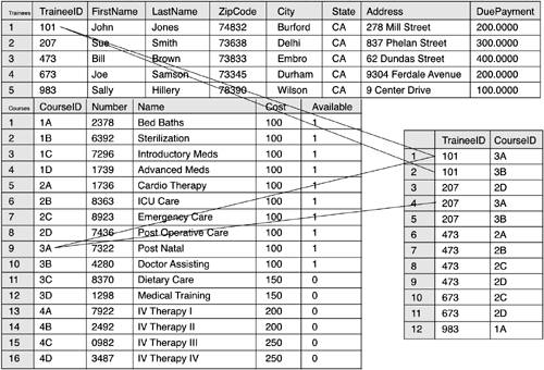
Now you can construct a general overview of what your model is going to look like. This is shown in Figure 2.3. Figure 2.3. ER model overview. So how are relationships actually implemented? They are implemented as parent and child entities. In all cases in the ER model, a key attribute from a child parent entity is attached to a related key value in a parent. All cardinality of relationships are implemented in this way. This means that whether you have a one-to-one, one-to-many, or many-to-many relationship, you always have the key of the child related to a parent. As noted previously in the chapter, many-to-many relationships exist when many instances of one entity are related to many instances of another entity. The reason why many-to-many relationships are implemented a bit differently is that the ER relational model does not support many-to-many relationships. Nonetheless, establish many-to-many relationships by creating two one-to-many relationships and connecting them to a new entity. This new entity is known as an associate entity or join entity . Resolving many-to-many relationships involves creating two one-to-many relationships from each of the original entities onto the associative entity. Take the many-to-many relationship between the Course entity and Trainee entity, for example. A many-to-many relationship needs to be resolved by creating an associative entity, TraineeCourse, and then linking a one-to-many relationship from the Course and Trainee entities to TraineeCourse. This process of resolving many-to-many relationships is shown in Figure 2.4. Figure 2.4. A many-to-many relationship. To help you better understand many-to-many relationships, the Course, Trainee, and Description entities along with sample data are shown in Figure 2.5. Figure 2.5. Sample data after a many-to-many resolution. One other many-to-many relationship also exists in the scenario. There is likely to be a many-to-many relationship between Employee and Machine, which is explored in the next section. Setting up the relationships finalizes a draft of the ER model. This draft will undergo modifications as the database approaches a physical design. The next topic to discuss is potential alteration to the design that will improve efficiency of the data store. REVIEW BREAK: Data Modeling OverviewWe have completed our look at the basic elements of data modeling using the Entity Relationship approach. A general listing of attributes for each entity and the relationships between these entities is an important springboard for progressing through the database design to the eventual completed system. Entities can correspond with each other in several different manners. If you look at a typical sales problem, it is easy to see some of these relationships. A salesman will have many customers, a customer will have many invoices, and an invoice will have many purchased products. The most common relationship is one-to-many, but the entire database system is sure to reveal a few many-to-many relationships as well. In the sales case, for example, many salesmen sell many products. Although you now have a general listing of entities, relationships, and attributes, the logical design is not yet complete. Next you need to fine-tune the model with a process called normalization . |
EAN: N/A
Pages: 228