5.3 Internet layer security protocols
5.3 Internet layer security protocols
In most network architectures and corresponding communications protocol stacks, network layer protocol data units are transmitted in the clear, meaning that they are not cryptographically protected during their transmission. Consequently, it is relatively simple to do malicious things, such as inspecting the contents of the data units, forging the source or destination addresses, modifying the contents, or even replaying old data units. There is no guarantee that data units received are in fact from the claimed originators (i.e., the claimed source addresses), that they are delivered to the proper recipients, that they contain the original contents, and that the contents have not been inspected by an eavesdropper while the data units were transmitted from the originators to the recipients. The lack of built-in security is particularly true for IP packets.
Against this background, the idea of having a standardized network or Internet layer security protocol (to protect network or Internet layer protocol data units) is not new, and several protocols had been proposed before the IETF IPSEC WG started to meet:
-
The Security Protocol 3 (SP3) was a network layer security protocol jointly developed and proposed by the U.S. National Security Agency (NSA) and the National Institute of Science and Technology (NIST) as part of the secure data network system (SDNS) suite of security protocols [23]. Outside the U.S. military, the SDNS and its security protocols have not seen widespread use. This is particularly true for SP3.
-
The Network Layer Security Protocol (NLSP) was developed by the ISO to secure the Connectionless Network Protocol (CLNP) [24]. Similar to IP in the Internet model, CLNP provides a connectionless and unreliable network layer service to the higher layers in the OSI reference model. As such, the aim of the NLSP is to secure the network layer service and to provide some basic security services to the higher layers . The NLSP is an incompatible descendent of SP3.
-
The Integrated NLSP (I-NLSP) was originally developed and proposed by the U.S. NIST to provide security services for both IP (i.e., IPv4) and CLNP. [6] Again, the security function of I-NLSP is roughly similar to that of SP3, although some details differ . For example, I-NLSP provides some additional functionality, such as security label processing.
-
A protocol named swIPe was yet another experimental Internet layer security protocol that was developed and prototyped by John Ioannidis and Matt Blaze [25]. The prototype implementation is publicly and freely available on the Internet. [7]
The network and Internet layer security protocols listed are more alike than they are different. In fact, they all use secure encapsulation as their basic enabling technique. What this basically means is that authenticated or encrypted network layer protocol data units are contained within other data units. In the case of secure IP encapsulation, for example, outgoing plaintext IP packets are authenticated or encrypted and encapsulated in new IP packets by adding new IP headers that are used to route the packets through the internetwork. At the peer systems, the incoming IP packets are decapsulated, meaning that the outer IP headers are stripped off and the inner IP packets are authenticated or decrypted and then forwarded to the intended recipients.
An encapsulated IP packet is illustrated in Figure 5.2. Note that the original IP header and IP payload (together with some additional data) are treated as the payload for the new IP packet, that this payload is the one that is protected, and that a new IP header must be prepended to the new payload. Consequently, the new IP header must not be encrypted, since it must be used to route (or tunnel) the new IP packet through the (inter)network. Such an encapsulation or tunneling scheme is convenient, since it means that no changes are required to the existing Internet routing infrastructure: authenticated or encrypted IP packets have an unencrypted, normal-looking outer IP header, and this IP header can be used to route and process the packet as usual. This transparency is convenient for the large-scale deployment of encapsulation and tunneling schemes in general, and IP encapsulation or tunneling in particular. In fact, similar IP encapsulation or tunneling schemes can be used to transfer multicast or IPv6 traffic through unicast or IPv4 networks.
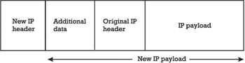
Figure 5.2: Encapsulated IP packet.
When the IETF started to develop the next version of IP (i.e., IPv6), it was commonly agreed that this version had to incorporate strong security features (at least for users who desire security). The security features had to be algorithm-independent so that the cryptographic algorithms could be altered without affecting the other parts of an implementation.
Furthermore, the security features should be useful in enforcing a wide variety of security policies, and yet they should be designed in a way that avoids adverse impacts on Internet users who do not need security services for the protection of their IP traffic at all.
Against this background, the IETF chartered an IPSEC WG in 1992. The aim was to define a security architecture ( mainly for IPv6), and to standardize both an IP Security Protocol (IPSP) and a related Internet Key Management Protocol (IKMP). Soon it was realized that the same security architecture that was being developed for IPv6 could also be used for IPv4. Consequently, the charter of the IETF IPSEC WG was revised to target both IPv6 and IPv4, and the resulting security architecture had to be the same. The main difference is that the security mechanisms specified in the IP security architecture have to be retrofitted into IPv4 implementations, whereas they must be present in all IPv6 implementations at the beginning.
In August 1995, the IETF IPSEC WG published a series of RFC documents that collectively specified a first version of the IP security architecture and the IPSP [26 “30]. This version was incomplete and rushed to publication, mainly to satisfy a perceived industry need. Nevertheless, the IESG approved the IPSP specification to enter the Internet standards track as a Proposed Standard, and the participants of the IETF IPSEC WG continued their work to refine the IP security architecture and the IPSP specification, as well as to standardize the IKMP [31, 32]. The discussion on the standardization of the IKMP was very controversial . In the end, two protocol proposals, namely, the Internet Security Association and Key Management Protocol (ISAKMP) and the OAKLEY Key Determination Protocol, were merged to become the IKMP. Furthermore, the acronym IPSP was replaced with the term IPsec protocols (as it consists of two subprotocols ), and the acronym IKMP was replaced with the term Internet Key Exchange (IKE). Consequently, the IP security architecture as we understand it today comprises both a set of IPsec protocols and the IKE protocol.
In November 1998, the IETF IPSEC WG published a series of RFC documents that collectively specify a revised version of the IP security architecture [33], including revised versions of the IPsec [34 “39] and IKE [40 “42] protocols. [8] In addition, an informational RFC was published that provides a road map for the various documents that are released under the auspices of the IETF IPSEC WG [43]. Further information about the current status of the various protocol specifications can be found on the home page of the IETF IPSEC WG. [9] In addition, there are several books that address IPsec and virtual private networking [44 “46]. Among these books, I particularly recommend [46].
Soon after the release of the revised series of RFC documents, it was realized that two topics deserved further study:
-
The use of policies in IPsec environments;
-
The use of IPsec technologies to secure remote access services. In early 2000, the IETF chartered an IP Security Policy (IPSP) [10] WG to address the first topic and an IP Security Remote Access (IPSRA) [11] WG to address the second topic. You may refer to the home pages of the two WGs to get an overview about the current status of their work.
5.3.1 IP security architecture
As mentioned above, the IP security architecture comprises an entire suite of security protocols. The suite includes the IPsec protocols and the IKE protocol. The IPsec protocols comprise the Authentication Header (AH) and Encapsulating Security Payload (ESP) subprotocols. Similarly, the IKE protocol has evolved from two major key management protocol proposals (i.e., ISAKMP and OAKLEY).
A high-level overview of the IP security architecture is given in Figure 5.3. In short, an IPsec module is a (hardware or software) module that implements the IPsec architecture and its protocols. The primary goal of an IPsec module is to secure IP traffic that is sent to or received from another IPsec module. What this basically means in terms of security services and mechanisms is specified in a corresponding security association (SA). The aim of the IKE protocol is to establish SAs and the aim of the IPsec protocols is to make use of these SAs. On either side of an SA, the security parameters of that SA (e.g., encryption algorithm and session key) are stored in a security association database (SAD). Each SA and corresponding entry in the SAD is indexed with three values:
-
A security parameters index (SPI);
-
An IP destination address;
-
A security protocol identifier (i.e., AH or ESP).
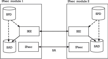
Figure 5.3: High-level overview of the IP security architecture.
As will be explained later, each IPsec-protected packet carries an SPI value that can be used by the recipient to retrieve the correct SA parameters from its SAD. In addition to the SAD, there is a security policy database (SPD) in each IPsec module. The SPD provides detailed specifications of the security services accorded to each packet.
In accordance with this high-level overview, the concept of an SA is at the core of the IP security architecture. An SA specifies the security services and mechanisms that must be implemented and used between two endpoints or IPsec modules. The endpoints, in turn , may be hosts or network security gateways, such as IPsec-enabled routers or application gateways. For example, an SA may require the provision of data confidentiality services through the use of the IPsec ESP protocol (this protocol will be explained later). Furthermore, the SA may specifiy the parameters for this protocol, such as the encryption algorithm (e.g., the DES algorithm), the mode of operation (e.g., the CBC mode), and its initialization vector (IV). The SA is a simplex (unidirectional) connection or relationship. Security services are afforded to an SA by the use of AH, or ESP, but not both. If both AH and ESP protection is applied to a data stream, then two SAs must be established and maintained . Similarly, to secure bidirectional communications between two hosts or security gateways, two SAs (one in each direction) are required. The term SA bundle refers to a set of SAs through which traffic must be processed to satisfy a specific security policy.
The IPsec architecture allows the user or system administrator to control the granularity at which security services are offered . In the first series of RFCs, three approaches toward how to feed SAs with security parameters and cryptographic keys were distinguished:
-
Host-oriented keying has all users on one host share the same session key for use on traffic destined for all users on another host.
-
User-oriented keying lets each user on one host have one or more unique session keys for the traffic destined for another host (such session keys are not shared with other users).
-
Session-unique keying has a single session key being assigned to a given IP address, upper-layer protocol, and port number triple (in this case, a user s FTP session may use a different key than the same user s Telnet session).
From a security point of view, user-oriented and session-unique keying are superior and therefore preferred. This is due to the fact that in many cases, a single computer system will have at least two suspicious users that do not mutually trust each other. When host-oriented keying is used and mutually suspicious users exist on a system, it is sometimes possible for a user to determine the host-oriented key by cryptanalytical attacks. Once this user has improperly obtained the key in use, he or she can either read another user s encrypted traffic or forge traffic from this particular user. Some possible attacks that follow and take advantage of this line of argumentation can be found in [47, 48]. When user-oriented or session-unique keying is used, certain kinds of attack from one user onto another user s data traffic are simply not possible. Unfortunately, the distinction between the three keying approaches is no longer used in the current protocol specifications of the IETF IPSEC WG. In reality, all we see today is host-oriented keying.
The SPD of an IPsec implementation defines at a high level of abstraction the security requirements for the IP packets that are forwarded or routed. As such, the SPD is established and maintained by a user or system administrator (or by an application operating within constraints established by either of them). Each entry in the SPD defines the traffic to be protected, how to protect it, and with whom the protection is shared. For each IP packet entering or leaving the IPsec implementation, the SPD must be consulted for the possible application of the IPsec security services. More specifically , an SPD entry may define one of the three actions to take upon a traffic match:
-
Discard: A packet is not let in or out.
-
Bypass: A packet is let in and out without applying IPsec security services.
-
Apply: A packet is only let in or out after having applied IPsec security services.
As such, the SPD provides access control enforcement equivalent to a (static) packet filter.
In general, the IPsec protocols (i.e., AH and ESP) are largely independent of the associated SA and key management techniques and protocols, although the techniques and protocols involved do affect some of the security services offered by the protocols. The IPsec protocols and the complementary IKE protocol are overviewed next.
5.3.2 IPsec protocols
According to the terminology introduced in the OSI security architecture, the IPsec protocols provide the following security services:
-
A data origin authentication service;
-
A connectionless data integrity service (including protection against replay attacks);
-
A data confidentiality service;
-
An access control service;
-
A limited traffic flow confidentiality service.
The security services are provided at the Internet layer, offering protection for IP and upper-layer protocols. As mentioned previously, the security services are provided by two subprotocols, namely, the AH and the ESP. Each protocol can be used to protect either only the upper-layer payload of an IP packet or the entire IP packet. This distinction is handled by considering two different modes of operation:
-
Transport mode is used to protect the upper-layer payload of an IP packet.
-
Tunnel mode is used to protect an entire IP packet (in this case, IP encapsulation is used as an enabling technique).
Figure 5.4 illustrates the IPsec transport and tunnel modes. In transport mode, an IPsec header (i.e., an AH or ESP header) is inserted between the original IP header and payload (i.e., the TCP segment or UDP datagram). In tunnel mode, the original IP packet is encapsulated into another IP packet. What this means is that there are two IP headers:
1. An inner IP header that carries the original IP header (specifying the original source and destination IP addresses);
2. An outer IP header that carries the new IP header (specifying new source and destination IP addresses).
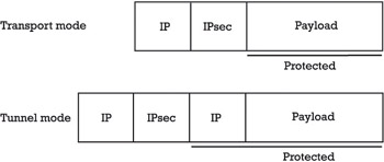
Figure 5.4: IPsec transport and tunnel modes.
The tunnel mode IPsec header appears between the outer IP header and the inner IP header.
Both IPsec protocols ”AH and ESP ”can operate in either transport or tunnel mode. Transport mode is typically used to secure IP traffic between two endpoints (i.e., computer systems), whereas tunnel mode is typically used to secure IP traffic between two points that are not necessarily the endpoints of the communications. For example, one of the points may be a security gateway for a corporate intranet. In this case, the IP traffic is encapsulated (i.e., using IPsec in tunnel mode) between the remote system and the security gateway (making sure that the systems located on the corporate intranet must not be able to handle IPsec). Note that whenever either endpoint is a security gateway (e.g., a router or firewall), IPsec must be used in tunnel mode (in the case where traffic is destined for a security gateway, e.g., SNMP commands, the security gateway is acting as a host, and transport mode is also allowed).
5.3.2.1 Authentication header
The IPsec AH protocol provides data origin authentication and connectionless data integrity for IP packets (collectively referred to as ˜ ˜authentication in this section). The precision of the authentication is a function of the granularity of the SA with which AH is employed. Depending on which cryptographic algorithm is used and how keying is performed, the AH may also provide non- repudiation of origin services. Finally, the AH may offer an antireplay service at the discretion of the receiver, to help counter specific DOS attacks.
The IANA has assigned the protocol number 51 for the AH protocol, so the header immediately preceding the AH must include 51 in its protocol or next header field. As specified in RFC 2402 [34] and illustrated in Figure 5.5, the AH header consists of the following fields:
-
An 8-bit Next Header field;
-
An 8-bit Payload Length field;
-
A 16-bit field that is reserved for future use;
-
A 32-bit SPI field;
-
A 32-bit Sequence Number field;
-
A variable-length n — 32-bit Authentication Data field.
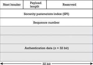
Figure 5.5: The authentication header (AH) format.
The authentication data is computed by using an authentication algorithm and a cryptographic key specified in the corresponding SA. The sender computes the data before sending the IP packet, and the receiver verifies it upon reception . Several algorithms for authentication data computation and verification have been proposed in the past. The HMAC construction is explained in [49]. In short, the HMAC construction takes as input the message M and the authentication key K , and produces as output the following expression:
HMAC K ( M ) = h(K ( opad , h(K ( ipad , M ))
To compute HMAC K (M) the key K and an inner pad value ipad ( ipad refers to the byte 0x36 repeated several times) are first added modulo 2. The result is concatenated with the message M and hashed with the OWHF h (which can be either MD5 or SHA-1). Similarly, the result is concatenated with the sum of K and an outer pad value opad ( opad refers to the byte 0x5C repeated several times) modulo 2. Finally, this result is hashed with the appropriate one-way hash function h (MD5 or SHA-1), and the resulting authentication data is truncated to 96 bits. 12 Depending on the OWHF in use, the resulting HMAC constructions are called HMAC-MD5-96 (in the case of MD5) and HMAC-SHA-1-96 (in the case of SHA-1).
@FN@The truncation was introduced because of a desire to achieve a specific packet alignment goal, to avoid devoting all 128 or 160 bits to the authentication function, and to have a uniform size MAC, whether MD5 or SHA-1 is employed. #FN#
Because the AH protocol does not provide data confidentiality services, implementations thereof may be widely deployed, even in countries where controls on encryption would preclude deployment of technology that potentially offered data confidentiality services. Consequently, AH is an appropriate protocol to employ when confidentiality is not required.
5.3.2.2 Encapsulating security payload
As its name suggests, the IPsec ESP protocol uses IP encapsulation to provide data confidentiality and partial traffic flow confidentiality (in tunnel mode and with the invocation of padding data to hide the size of an IP packet). Similar to the AH, the ESP protocol also provides authentication (referring to data origin authentication and connectionless data integrity services). Note, however, that the scope of the authentication offered by the ESP is narrower than that for the AH (i.e., the IP headers below the ESP header are not protected). If only the upper-layer protocols need to be authenticated, then ESP authentication is an appropriate choice and is more space efficient than use of an AH encapsulating an ESP.
The IANA has assigned the protocol number 50 for the ESP protocol, so the header immediately preceding the ESP must include 50 in its protocol or next header field. The ESP format is specified in RFC 2406 [38] and illustrated in Figure 5.6. It consists of the following fields:
-
A 32-bit SPI field (not encrypted);
-
A 32-bit Sequence Number field (not encrypted);
-
A variable-length Payload Data field;
-
A variable-length Padding field;
-
An 8-bit Pad Length field;
-
An 8-bit Next Header field;
-
In addition, the ESP may also include a variable-length n *32-bit Authentication Data field.
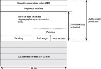
Figure 5.6: The encapsulating security payload (ESP) format.
In RFC 2405, the DES in cipher block chaining (CBC) mode with an explicit initialization vector (IV) is introduced as the default algorithm to encrypt the ESP Payload Data field [37]. But this default algorithm may be replaced by any other algorithm at will. For example, RFC 1851 specifies the experimental use of 3DES. In the future, it is possible and very likely that we will see more AES implementations instead of DES or 3DES
implementations. Unfortunately, export, import, and use of specific encryption algorithms may be regulated in some countries. The algorithms for computing the authentication data are the same as the ones suggested for the AH.
Note that both AH and ESP are also vehicles for access control, based on the distribution of cryptographic keys and the management of traffic flows relative to these security protocols. Also note that full protection from traffic analysis is not provided by any of the two IPsec subprotocols. At the most, tunnel mode ESP can provide a partial traffic flow confidentiality service. In fact, the ESP protocol can be used to create a secure tunnel between two security gateways. In this case, anyone eavesdropping on the
communications between the security gateways is not able to see what hosts are actually sending and receiving IP packets from behind the security gateways. Nevertheless, it is fair to mention that only a few Internet users worry about traffic analysis at all.
5.3.3 IKE Protocol
The IP security architecture mandates support for both manual and automated SA and key management (using a key management protocol). For several years , the IETF IPSEC WG had been struggling with competing proposals for an automated SA and key management protocol:
-
IBM proposed a Modular Key Management Protocol (MKMP) for its IP Secure Tunnel Protocol (IPST) [50].
-
Sun Microsystems proposed and is using its Simple Key-Management for Internet Protocols (SKIP) [51].
-
Phil Karn originally proposed and prototyped a Photuris Key Management Protocol [13] [52, 53] that is conceptually similar to the Station-to-Station (STS) protocol originally proposed in [54]. The Photuris protocol combines an ephemeral Diffie-Hellman key exchange with a subsequent authentication step to protect against man-in-the-middle attacks. To protect the participanting peers against resource clogging attacks, the Photuris protocol introduced a cookie exchange.
-
Hugo Krawczyk proposed a variation and generalization of the Photuris protocol, called Photuris Plus or SKEME [55].
-
Because Bill Simpson (one of the coauthors of the latest Photuris Key Management Protocol specification) refused to make changes to protocol specification in accordance with suggestions provided by the IETF IPSEC WG chairs, the Photuris Key Management Protocol was dropped from consideration and Hilarie Orman drafted a version of the Photuris and SKEME protocols that was called OAKLEY Key Determination Protocol [56]. In this protocol, several parameters are negotiable, including, for example, the mathematical structure in which the Diffie-Hellman key exchange is supposed to take place and the authentication method that is being used.
-
The NSA Office of INFOSEC Computer Science proposed a general Internet Security Association and Key Management Protocol (ISAKMP).
In the first half of the 1990s, the developers of the various key management protocols competed with one another within the IETF IPSEC WG. There were basically two groups: (1) SKIP and (2) the group of Photuris-like protocols, including, for example, the OAKLEY Key Determination Protocol. Also, because of the fact that SKIP does not make use of SAs at all, the ISAKMP is useful only for the protocols of group (b). Consequently, the two major contenders were SKIP and ISAKMP/OAKLEY.
In September 1996, the IETF Security Area Director [14] posted a document to the Internet to end the controversy. In this document, the two contenders (i.e., SKIP and ISAKMP/OAKLEY) were reviewed, and it was concluded that ISAKMP/OAKLEY should become the mandatory standard (SKIP can still become an elective standard).
In short, ISAKMP defines how two peers communicate, how the messages they use to communicate are constructed , and through which state transitions they go to secure their communications. It provides the means to authenticate a peer, to exchange information for a key exchange, and to negotiate security services. It does not, however, define how a particular authenticated key exchange is done, nor does it define the attributes necessary for an SAs. These issues are left to a specific key exchange protocol, such as OAKLEY. As such, ISAKMP is a general-purpose security exchange protocol that may be used for policy negotiation and establishment of keying material for a variety of needs. The specification of what IKE is being used for is done in a domain of interpretation (DOI). The IP security DOI for ISAKMP is specified in RFC 2407 [40]. More specifically, RFC 2407 defines how ISAKMP can be used to negotiate IKE and IPsec SAs. If and when IKE is used by other protocols, they will each have to define their own DOI. [15] In other words, ISAKMP defines the language to establish authenticated session keys, whereas OAKLEY defines the steps two peers must actually take to establish the keys. Together they constitute the IKE protocol.
The IKE protocol is a request-response type of protocol with an initiator and a responder . The IKE initiator is the party that is instructed by its IPsec module to establish an SA or SA bundle as a result of an outbound packet matching an SPD entry. The SPD of IPsec is used to instruct IKE what to establish but does not instruct IKE how to do so. In fact, how IKE establishes the IPsec SAs is based on its own policy settings. IKE defines policy in terms of protection suites. Each protection suite must define at least an encryption algorithm, a hash algorithm, a Diffie-Hellman group, and a method for authentication. IKE s policy database then is the list of all protection suites weighted in order of preference.
The establishment of an IPsec SA (or an SA bundle) using IKE is a two-phase process:
-
In phase one, an IKE SA is established. The IKE SA defines the way in which the two peers communicate, for example, which algorithm to use to encrypt IKE traffic, how to authenticate the remote peer, and so on.
-
In phase two, the IKE SA is used to establish any given number of IPsec SAs between the communicating peers. The IPsec SAs established by IKE may optionally have perfect forward secrecy (PFS [16] ) of the keys and, if desired, also of the peer identity.
5.3.3.1 Phase one: establishing an IKE SA
The establishment of an IKE SA basically consists of three steps and corresponding exchanges:
1. A cookie exchange;
2. A value exchange;
3. An authentication exchange. In short, the cookie exchange protects the responder from simple resource clogging attacks. Once initiator and responder cookies have been established, a value exchange and a subsequent authentication exchange are used to implement an authenticated Diffie-Hellman key exchange, and to provide the initiator and responder with an authenticated shared secret accordingly .
Cookie Exchange: To protect the responder from simple resource clogging attacks, the initiator must provide a valid cookie whenever he or she wants to enter a value exchange and initiate a computationally expensive Diffie-Hellman key exchange accordingly. A valid cookie, in turn, is a value that can be computed and verified only by the responder. For example, it can be a keyed one-way hash value of the initiator s and responder s IP addresses and port numbers . In this case, the key must be known only to the responder.
Value Exchange: A value exchange establishes a shared secret key between the communicating peers. In general, there is more than one way to establish a key, but IKE always uses a Diffie-Hellman key exchange. Consequently, the act of doing a Diffie-Hellman key exchange is not negotiable, but the parameters to use are. In fact, IKE borrows five groups from the OAKLEY specification; three are traditional exchanges doing exponentiation modulo a large prime, and two are elliptic curve groups. Upon completion of the value exchange, the two peers share a key and this key still needs to be authenticated.
Authentication Exchange: In a final step, the Diffie-Hellman key and, therefore, the IKE SA must be authenticated. There are five methods of authentication defined in IKE: preshared keys, digital signature using DSS, digital signature using RSA, and two methods that use an encrypted nonce exchange with RSA.
There are basically two modes and corresponding exchanges that can be used in phase one: a main mode exchange and an aggressive mode exchange.
-
In a main mode exchange , the request and response messages for each of the three exchanges are sent and received one after the other, totaling six messages.
-
Contrary to that, some of the messages are sent together in an aggressive mode exchange , totaling three messages. Most important, an aggressive mode exchange cannot use cookies to protect against resource clogging attacks.
In short, aggressive mode is faster but main mode is more flexible. Once Phase One is completed, Phase Two may commence and the required IPsec SAs may be created.
5.3.3.2 Phase two: establishing IPsec Sas
Contrary to Phase One, there is a single Phase Two exchange, and this exchange has been named quick mode exchange. This exchange negotiates IPsec SAs under the protection of the IKE SA, which was created in Phase One. The keys used for the IPsec SAs are, by default, derived from the IKE secret state. Pseudorandom nonces are exchanged in quick mode and hashed with the secret state to generate keys and guarantee that all SAs have unique keys. All such keys do not have the property of PFS as they are all derived from the same root key (i.e., the IKE shared secret). To provide PFS, Diffie-Hellman public values, and the group from which they are derived, are exchanged along the nonces and IPsec SA negotiation parameters. The resulting secret is used to generate the IPsec SA keys to guarantee PFS.
5.3.4 Implementations
As illustrated in Figure 5.7, there are three possibilities to implement the IPsec architecture (with or without key management) and to place the implementation in a host or security gateway:
-
The most simple and straightforward possibility is to integrate the IPsec protocols into a native IP implementation (a). This is applicable to hosts and security gateways, but requires access to the corresponding source code.
-
Another possibility is provided by so-called bump-in-the-stack (BITS) implementations (b). In these implementations, IPsec is implemented underneath an existing IP stack, between the native IP implementation and the local network drivers. Source code access for the IP stack is not required in this case, making it appropriate for use with legacy systems. This approach, when adopted, is usually employed with hosts.
-
A somewhat related possibility is provided by so-called bump-in-the-wire (BITW) implementations (c). Similar to BITS implementations, source code access for the IP stack is not required for BITW implementations. But in addition to BITS implementations, additional hardware in the form of outboard cryptographic processors are typically used. This is a common design feature of network security systems used by the military, and of some commercial systems as well. BITW implementations may be designed to serve both hosts and security gateways.
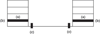
Figure 5.7: The three possibilities to implement the IPsec architecture.
As of this writing, most IPsec implementations are either BITS or BITW. For example, PGPnet is a BITS implementation, whereas most firewall products that support IPsec for virtual private networking are BITW implementations. The dominance of BITS or BITW implementations is expected to change in the future, because more vendors of networking software have integrated or are about to integrate the IPsec protocols into their products. For example, Windows 2000 comes along with IPsec support and the Cisco IOS also provides support for the IPsec protocols in the more recent releases.
From an implementation point of view, it is important that the key management protocol in use (e.g., IKE protocol) implements a standardized API. The IETF IPSEC WG has specified a corresponding PF KEY key management API version 2 [57].
There are advantages and disadvantages related to security protocols that operate at the Internet layer in general, and the IPsec protocols in particular:
-
The main advantage is that applications need not be changed to use the IPsec protocols. Another advantage is that providing security at the Internet layer works for both TCP- and UDP-based applications. This is advantageous because a steadily increasing number of applications are based on UDP that is hard to secure at the transport layer.
-
The main disadvantage is that IP stacks must either be changed or extended. Because of the inherent complexity of the IKE protocol, the changes or extensions are not trivial. In the long term, high-speed networking may also provide a performance problem. As of this writing, it is not clear whether encryption rates and key agility properties of IPsec implementations will meet the performance requirements of future high-speed networks.
Because of the disadvantages of providing security at the Internet layer, some alternative approaches have appeared in the past (as discussed in the other sections of this chapter). The current trend in industry suggests that the IPsec protocols will primarily be used for virtual private networking and connecting mobile users to corporate intranets .
[6] Note that the IETF PPPEXT WG is situated in the IETF s Internet area (not in the security area).
[7] I-NLSP was specified in an Internet-Draft that expired long ago.
[8] ftp://ftp.csua.berkeley.edu/pub/cypherpunks/swIPe/swipe.tar.Z
[9] As of this writing, the protocol specifications refer to proposed standards.
[10] http://www.ietf.org/html. charters /ipsec-charter.html
[11] http://www.ietf.org/html.charters/ipsp-charter.html
[13] http://www.ietf.org/html.charters/ipsra-charter.html
[14] Phil Karn was later joined by Bill Simpson to write the experimental Photuris protocol specifications.
[15] The IETF Security Area Director was (and still is) Jeffrey Schiller from MIT.
[16] At the time of this writing, no other DOI is available.
EAN: 2147483647
Pages: 142