How the System Finds and Loads Drivers
How the System Finds and Loads Drivers
I emphasized in the preceding section how the operating system is in overall charge of the computer and calls on device drivers to do small amounts of work with respect to hardware. Drivers have a similarly passive role in the process that causes them to be loaded in the first place. It will help you understand the rest of the book if you understand right away how the system detects hardware, determines which driver to load, and then configures the driver to manage the hardware. The system uses two slightly different methods, depending on whether the hardware is Plug and Play compatible:
-
A Plug and Play device has an electronic signature that the system can detect. For Plug and Play devices, a system bus driver detects the existence of the hardware and reads the signature to determine what kind of hardware it is. Thereafter, an automatic process based on the registry and INF files allows the system to load the right driver.
-
A legacy device does not have any electronic signature, so the system can t detect it automatically. The end user must therefore initiate the detection process by invoking the Add New Hardware Wizard, which ends with the system knowing that a certain new piece of hardware exists. Thereafter, the system uses the same automatic registry-and-INF-file process that s used for Plug and Play devices to load the right driver.
Whichever method the system uses to detect hardware and load a driver, the driver itself will be a WDM driver that reacts passively to calls from the operating system. On this point, WDM drivers contrast sharply with kernel-mode drivers for earlier versions of Windows NT and with VxD drivers prior to Windows 95. In those environments, you had to somehow arrange for the system to load your driver. Your driver would then scan hardware buses looking for its own hardware and decide whether to stay resident or not. In addition, your driver had to determine which I/O resources to use and take steps to prevent other drivers from taking the same resources.
Device and Driver Layering
Before I can make sense of the hardware detection and driver loading processes, I need to explain the concept of driver layering illustrated in Figure 2-2. In the figure, the left column represents an upwardly linked stack of kernel DEVICE_OBJECT structures, all of which relate to how the system manages a single piece of hardware. The middle column represents the collection of device drivers that have roles to play in the management. The right column illustrates the flow of an IRP through the drivers.
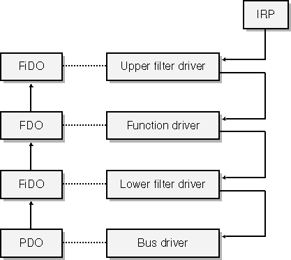
Figure 2-2. Layering of device objects and drivers in the Windows Driver Model.
In the Windows Driver Model, each hardware device has at least two device drivers. One of these drivers, which we call the function driver, is what you ve always thought of as being the device driver. It understands all the details about how to make the hardware work. It s responsible for initiating I/O operations, for handling the interrupts that occur when those operations finish, and for providing a way for the end user to exercise any control over the device that might be appropriate.
NOTE
A monolithic WDM function driver is a single executable file with dynamic links to NTOSKRNL.EXE, which contains the kernel of the operating system, and HAL.DLL, which contains the hardware abstraction layer (HAL). A function driver can dynamically link to other kernel-mode DLLs too. In situations in which Microsoft has provided a class driver for your type of hardware, your minidriver will dynamically link to the class driver. The combination of minidriver and class driver adds up to a single function driver. You may see pictures in which things called class drivers appear to be above or below a minidriver. I prefer to think of those so-called class drivers as free-standing filter drivers and to use the term class driver solely for drivers that are next to minidrivers, reached by means of explicit imports, and acting as partners that the minidriver willingly brings into play.
We call the other of the two drivers that every device has the bus driver. It s responsible for managing the connection between the hardware and the computer. For example, the bus driver for the Peripheral Component Interconnect (PCI) bus is the software component that actually detects that your card is plugged into a PCI slot and determines the requirements your card has for I/O-mapped or memory-mapped connections with the host. It s also the software that turns on or off the flow of electrical current to your card s slot.
Some devices have more than two drivers. We use the generic term filter driver to describe these other drivers. Some filter drivers simply watch as the function driver performs I/O. More often, a software or hardware vendor supplies a filter driver to modify the behavior of an existing function driver in some way. Upper filter drivers see IRPs before the function driver, and they have the chance to support additional features that the function driver doesn t know about. Sometimes an upper filter can perform a workaround for a bug or other deficiency in the function driver or the hardware. Lower filter drivers see IRPs that the function driver is trying to send to the bus driver. (A lower filter is below the function driver in the stack but still above the bus driver.) In some cases, such as when the device is attached to a universal serial bus (USB), a lower filter can modify the stream of bus operations that the function driver is trying to perform.
Referring once again to Figure 2-2, notice that each of the four drivers shown for a hypothetical device has a connection to one of the DEVICE_OBJECT structures in the left column. The acronyms used in the structures are these:
-
PDO stands for physical device object. The bus driver uses this object to represent the connection between the device and the bus.
-
FDO stands for function device object. The function driver uses this object to manage the functionality of the device.
-
FiDO stands for filter device object. A filter driver uses this object as a place to store the information it needs to keep about the hardware and its filtering activities. (The early beta releases of the Windows 2000 DDK used the term FiDO, and I adopted it then. The DDK no longer uses this term because, I guess, it was considered too frivolous.)
What Is a Bus?
I ve already used the terms bus and bus driver pretty freely without explaining what they mean. For purposes of the WDM, a bus is anything that you can plug a device into, either physically or metaphorically.This is a pretty broad definition. Not only does it include items such as the PCI bus, but it also includes a Small Computer System Interface (SCSI) adapter, a parallel port, a serial port, a USB hub, and so on anything, in fact, that can have another device plugged into it.
The definition also includes a notional root bus that exists only as a figment of our imagination. Think of the root bus as being the bus into which all legacy devices plug. Thus, the root bus is the parent of a non-PnP Industry Standard Architecture (ISA) card or of a SmartCard reader that connects to the serial port but doesn t answer with a standard identification string to the serial port enumeration signals. We also consider the root bus to be the parent of the PCI bus this is because the PCI bus does not itself announce its presence electronically, and the operating system therefore has to treat it like a legacy device.
Plug and Play Devices
To repeat what I said earlier, a Plug and Play device is one that has an electronic signature that a bus driver can interrogate to learn the identity of a device. Here are some examples of these signatures:
-
A PCI card has a configuration space that the PCI bus driver can read via dedicated memory or I/O port addresses. The configuration space contains vendor and product identification information.
-
A USB device returns a device descriptor in response to a standardized control-pipe transaction. The device descriptor contains vendor and product identification information.
-
A Personal Computer Memory Card International Association (PCMCIA) device has attribute memory that the PCMCIA bus driver can read in order to determine the identity of the card.
A bus driver for a Plug and Play bus has the ability to enumerate its bus by scanning all possible slots at start-up time. Drivers for buses that support hot plugging of devices during a session (as do USB and PCMCIA) also monitor some sort of hardware signal that indicates arrival of a new device, whereupon the driver reenumerates its bus. The end result of the enumeration or reenumeration process is a collection of PDOs. See point 1 in Figure 2-3.
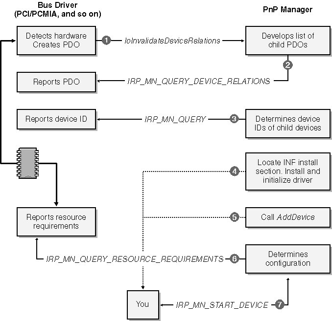
Figure 2-3. Installing a Plug and Play device.
When a bus driver detects the insertion or removal of hardware, it calls IoInvalidateDeviceRelations to notify the PnP Manager that the bus s population of child devices has changed. To obtain an updated list of the PDOs for the child devices, the PnP Manager sends an IRP to the bus driver. The major function code for this IRP is IRP_MJ_PNP, and the minor function code is IRP_MN_QUERY_DEVICE_RELATIONS, with a code indicating that the PnP Manager is looking for the so-called bus relations. This is point 2 in Figure 2-3.
NOTE
Each IRP has a major and a minor function code. The major function code indicates what sort of request the IRP contains. IRP_MJ_PNP is the major function code for requests that the PnP Manager makes. With some of the major function codes, including IRP_MJ_PNP, the minor function code is required to further specify the operation.
In response to the bus relations query, the bus driver returns its list of PDOs. The PnP Manager can easily determine which of the PDOs represent devices that it hasn t yet initialized. Let s focus on the PDO for your hardware for the time being and see what happens next.
The PnP Manager will send another IRP to the bus driver, this time with the minor function code IRP_MN_QUERY_ID. This is point 3 in Figure 2-3. In fact, the PnP Manager sends several such IRPs, each with an operand that instructs the bus driver to return a particular type of identifier. One of the identifiers, the device identifier, uniquely specifies the type of device. A device identifier is just a string, and it might look like one of these examples:
PCI\VEN_102C&DEV_00E0&SUBSYS_00000000 USB\VID_0547&PID_2125&REV_0002 PCMCIA\MEGAHERTZ-CC10BT/2-BF05
NOTE
Each bus driver has its own scheme for formatting the electronic signature information it gathers into an identifier string. I ll discuss the identifier strings used by common bus drivers in Chapter 15. That chapter is also the place to look for information about INF files and about where the various registry keys described in the text are in the registry hierarchy and what sorts of information are kept in the keys.
The PnP Manager uses the device identifier to locate a hardware key in the system registry. For the moment, let s assume that this is the first time your particular device has been plugged into the computer. In that case, there won t yet be a hardware key for your type of device. This is where the setup subsystem steps in to figure out what software is needed to support your device. (See point 4 in Figure 2-3.)
Installation instructions for all types of hardware exist in files with the extension .INF. Each INF contains one or more model statements that relate particular device identifier strings to install sections within that INF file. Confronted with brand-new hardware, then, the setup subsystem tries to find an INF file containing a model statement that matches the device identifier. It will be your responsibility to provide this file, which is why I labeled the box You that corresponds to this step. I m being deliberately vague at this point about how the system searches for INF files and ranks the several model statements it s likely to find. I ll burden you with these details in Chapter 15, but it would be a bit much to do that just yet.
When the setup subsystem finds the right model statement, it carries out the instructions you provide in an install section. These instructions probably include copying some files onto the end user s hard drive, defining a new driver service in the registry, and so on. By the end of the process, the setup program will have created the hardware key in the registry and installed all of the software you provided.
Now step back a few paragraphs and suppose that this was not the first time this particular computer had seen an instance of your hardware. For example, maybe we re talking about a USB device that the user introduced to the system long ago and that the user is now reattaching to the system. In that case, the PnP Manager would have found the hardware key and would not have needed to invoke the setup program. So the PnP Manager would skip around all the setup processing to point 5 in Figure 2-3.
At this point, the PnP Manager knows there is a device and that your driver is responsible for it. If your driver isn t already loaded in virtual memory, the PnP Manager calls the Memory Manager to map it in. The system doesn t read the disk file containing your driver directly into memory. Instead, it creates a file mapping that causes the driver code and data to be fetched by paging I/O. The fact that the system uses a file mapping really doesn t affect you much except that it has the side effect of making you be careful later on about when you allow your driver to be unmapped. The Memory Manager then calls your DriverEntry routine.
Next the PnP Manager calls your AddDevice routine to inform your driver that a new instance of your device has been discovered. (See point 5 in Figure 2-3.) Then the PnP Manager sends an IRP to the bus driver with the minor function code IRP_MN_QUERY_RESOURCE_REQUIREMENTS. This IRP is basically asking the bus driver to describe the requirements your device has for an interrupt request line, for I/O port addresses, for I/O memory addresses, and for system DMA channels. The bus driver constructs a list of these resource requirements and reports them back. (See point 6 in Figure 2-3.)
Finally the PnP Manager is ready to configure the hardware. It works with a set of resource arbitrators to assign resources to your device. If that can be done and it usually can be the PnP Manager sends an IRP_MJ_PNP to your driver with the minor function code IRP_MN_START_DEVICE. Your driver handles this IRP by configuring and connecting various kernel resources, following which your hardware is ready to use.
Windows NT Drivers Contrasted
The process described in the text for how Windows XP (and, indeed, Windows 2000, Windows 95, and all successors of Windows 95) finds and loads drivers requires the driver to be relatively passive. Windows NT 4.0 and before worked quite differently. In those systems, you would have provided some sort of setup program to install your driver. Your setup program would have modified the registry to cause your driver to be loaded during the next system restart. At that time, the system would load your driver and call your DriverEntry routine.Your DriverEntry would have somehow determined which instances of your hardware were actually present. You might have scanned all possible slots of a PCI bus, for example, or assumed that each instance of your device corresponded to a subkey in the registry.
After detecting your own hardware, your DriverEntry routine would go on to assign and reserve I/O resources and then to do the configuration and connection steps that a present-day WDM driver does. As you can see, then, WDM drivers have much less work to do to get started than did drivers for earlier versions of Windows NT.
Legacy Devices
I use the term legacydevice to describe any device that isn t Plug and Play, meaning that the operating system can t detect its existence automatically. Let s suppose your device fits this category. After purchasing your device, the end user will first invoke the Add New Hardware Wizard and will make a series of dialog selections to lead the setup program to an install section in an INF file. (See Figure 2-4, point 1.)
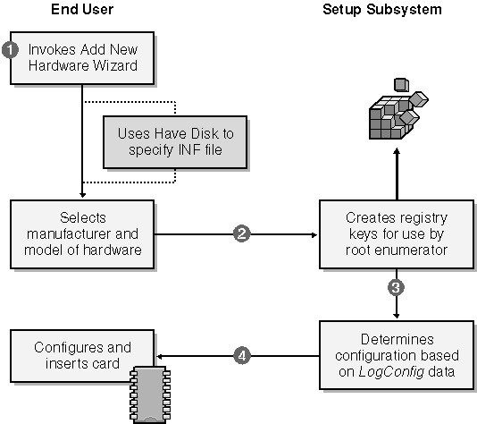
Figure 2-4. The detection process for a legacy device.
The setup program follows the instructions in the install section by creating registry entries for use by the root enumerator (point 2 in Figure 2-4). The registry entries might include a logical configuration that lists the I/O resource requirements for the device (point 3).
Finally the setup program instructs the end user to restart the system (point 4). The designers of the setup system expected that the end user would now need to follow the manufacturer s directions to configure the card by setting jumpers or switches and would then need to insert the card into an expansion slot of a powered-down computer.
Following the restart (or following the end user s decision to bypass the restart), the root enumerator will scan the registry and find the newly added device. Thereafter, the process of loading your driver is nearly identical to that for a Plug and Play device. See Figure 2-5.
NOTE
Most of the sample drivers in the companion content are for fake hardware, and you install them as if the (nonexistent) hardware were a legacy device. One or two of the samples work with I/O ports and interrupts. The respective INF files contain LogConfig sections to cause the PnP Manager to assign these resources. If you install one of these drivers via the Add New Hardware Wizard, the system will think that a power-off restart is needed, but you don t really need to restart.
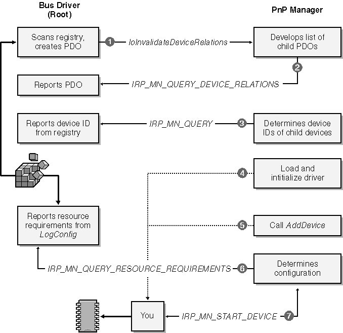
Figure 2-5. Loading a legacy driver.
Recursive Enumeration
In the preceding sections, I described how the system loads the correct driver for a single device. That description begs the question of how the system manages to load drivers for all the hardware in the computer. The answer is that it uses a recursive process.
In the first instance, the PnP Manager invokes the root enumerator to find all hardware that can t electronically announce its presence including the primary hardware bus (such as PCI). The root bus driver gets information about the computer from the registry, which was initialized by the Windows XP Setup program. Setup got the information by running an elaborate hardware detection program and by asking the end user suitable questions. Consequently, the root bus driver knows enough to create a PDO for the primary bus.
The function driver for the primary bus can then enumerate its own hardware electronically. When a bus driver enumerates hardware, it acts in the guise of an ordinary function driver. Having detected a piece of hardware, however, the driver switches roles: it becomes a bus driver and creates a new PDO for the detected hardware. The PnP Manager then loads drivers for this device PDO, as previously discussed. It might happen that the function driver for the device enumerates still more hardware, in which case the whole process repeats recursively. The end result will be a tree like that shown in Figure 2-6, wherein a bus-device stack branches into other device stacks for the hardware attached to that bus. The dark-shaded boxes in the figure illustrate how one driver can wear an FDO hat to act as the function driver for its hardware and a PDO hat to act as the bus driver for the attached devices.
Order of Driver Loading
I said earlier that devices can have upper and lower filter drivers as well as a function driver. Two registry keys associated with the device contain information about filter drivers. The device key, which contains information about an instance of your hardware, can have UpperFilters and LowerFilters values that specify filter drivers for that instance. There is another registry key for the class to which the device belongs. For example, a mouse belongs to the Mouse class, which you could probably have figured out without me telling you. The class key can also contain UpperFilters and LowerFilters values. They specify filter drivers that the system will load for every device belonging to the class.
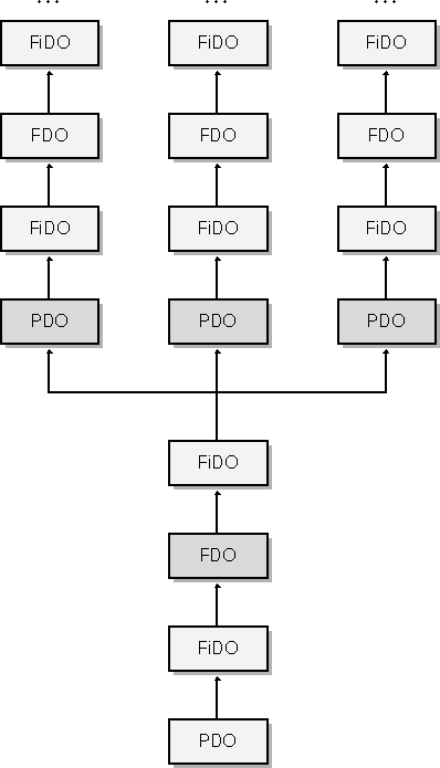
Figure 2-6. Layering of recursively enumerated devices.
No matter where it appears, an UpperFilters or LowerFilters value is of type REG_MULTI_SZ and can therefore contain one or more null-terminated Unicode string values.
NOTE
Windows 98/Me doesn t support the REG_MULTI_SZ registry type and doesn t fully support Unicode. In Windows 98/Me, the UpperFilters and LowerFilters values are REG_BINARY values that contain multiple null-terminated ANSI strings followed by an extra null terminator.
It may be important in some situations to understand in what order the system calls drivers. The actual process of loading a driver entails mapping its code image into virtual memory, and the order in which that s done is actually not very interesting. You might be interested, however, in knowing the order of calls to the AddDevice functions in the various drivers. (Refer to Figure 2-7.)
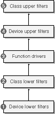
Figure 2-7. Order of AddDevice calls.
-
The system first calls the AddDevice functions in any lower filter drivers specified in the device key for the device, in the order in which they appear in the LowerFilters value.
-
Then the system calls AddDevice in any lower filter drivers specified in the class key. Again, the calls occur in the order in which the drivers appear in the LowerFilters string.
-
The system calls AddDevice in the driver specified by the Service value in the device key. This is the function driver.
-
The system calls AddDevice for any upper filter drivers specified in the device key, in the order in which they appear in the UpperFilters data string.
-
Finally the system calls AddDevice for any upper filter drivers specified in the class key, in the order in which they appear in the UpperFilters data string.
As I explain later in this chapter, each AddDevice function creates a kernel DEVICE_OBJECT and links it into the stack rooted in the PDO. Therefore, the order of calls to AddDevice governs the order of device objects in the stack and, ultimately, the order in which drivers see IRPs.
NOTE
You might have noticed that the loading of upper and lower filters belonging to the class and to the device instance isn t neatly nested as you might have expected. Before I knew the facts, I guessed that device-level filters would be closer to the function driver than class-level filters.
IRP Routing
The formal layering of drivers in the WDM facilitates routing IRPs from one driver to another in a predictable way. Figure 2-2 illustrates the general idea: whenever the system wants to carry out an operation on a device, it sends an IRP to the topmost filter driver in the stack. That driver can decide to process the IRP, to pass the IRP down to the next level, or to do both. Each driver that sees the IRP makes the same decision. Eventually, the IRP might reach the bus driver in its PDO role. The bus driver does not usually pass the IRP any further, despite what Figure 2-6 might seem to imply. Rather, the bus driver usually completes the IRP. In some situations, the bus driver will pass the same IRP to the stack (the parent driver stack) in which it plays the FDO role. In other situations, the bus driver will create a secondary IRP and pass it to the parent driver stack.
How the Device Stack Is Implemented
I ll show you the DEVICE_OBJECT data structure a bit later in this chapter. The opaque field AttachedDevice links device objects into a vertical stack. Starting with the PDO, each device object points to the object immediately above it. There is no documented downward pointer drivers must keep track on their own of what s underneath them. (In fact, IoAttachDeviceToDeviceStack does set up a downward pointer in a structure for which the DDK doesn t have a complete declaration. It would be unwise to try to reverse-engineer that structure because it s subject to change at any time.)The AttachedDevice field is purposely not documented because its proper use requires synchronization with code that might be deleting device objects from memory. You and I are allowed to call IoGetAttachedDeviceReference to find the topmost device object in a given stack. That function also increments a reference count that will prevent that object from being prematurely removed from memory. If you wanted to work your way down to the PDO, you could send your own device an IRP_MJ_PNP request with the minor function code IRP_MN_QUERY_DEVICE_RELATIONS and the Type parameter TargetDeviceRelation. The PDO s driver will answer by returning the address of the PDO. It would be a great deal easier just to remember the PDO address when you first create the device object.
Similarly, to know which device object is immediately underneath you, you need to save a pointer when you first add your object to the stack. Since each of the drivers in a stack will have its own unknowable way of implementing the downward pointers used for IRP dispatching, it s not practical to alter the device stack once the stack has been created.
A few examples should clarify the relationship between FiDOs, FDOs, and PDOs. The first example concerns a read operation directed to a device that happens to be on a secondary PCI bus that itself attaches to the main bus through a PCI-to-PCI bridge chip. To keep things simple, let s suppose there s one FiDO for this device, as illustrated in Figure 2-8. You ll learn in later chapters that a read request turns into an IRP with the major function code IRP_MJ_READ. Such a request would flow first to the upper FiDO and then to the function driver for the device. (That driver is the one for the device object marked FDOdev in the figure.) The function driver calls the HAL directly to perform its work, so none of the other drivers in the figure will see the IRP.
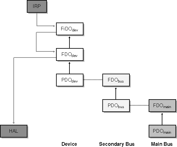
Figure 2-8. The flow of a read request for a device on a secondary bus.
A variation on the first example is shown in Figure 2-9. Here we have a read request for a device plugged into a USB hub that itself is plugged into the host controller. The complete device tree therefore contains stacks for the device, for the hub, and for the host controller. The IRP_MJ_READ flows through the FiDO to the function driver, which then sends one or more IRPs of a different kind downward to its own PDO. The PDO driver for a USB device is USBHUB.SYS, and it forwards the IRPs to the topmost driver in the host controller device stack, skipping the two-driver stack for the USB hub in the middle of the figure.
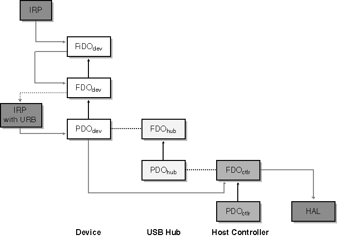
Figure 2-9. The flow of a read request for a USB device.
The third example is similar to the first except that the IRP in question is a notification concerning whether a disk drive on a PCI bus will be used as the repository for a system paging file. You ll learn in Chapter 6 that this notification takes the form of an IRP_MJ_PNP request with the minor function code IRP_MN_DEVICE_USAGE_NOTIFICATION. In this case, the FiDO driver passes the request to the FDOdev driver, which takes note of it and passes it further down the stack to the PDOdev driver. This particular notification has implications about how other I/O requests that concern the PnP system or power management will be handled, so the PDOdev driver sends an identical notification to the stack within which is the FDObus, as illustrated in Figure 2-10. (Not all bus drivers work this way, but the PCI bus does.)
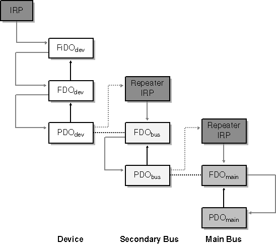
Figure 2-10. The flow of a device usage notification.
Visualizing the Device Tree
To better visualize the way device objects and drivers are layered, it helps to have a tool. I wrote the DEVVIEW utility, which you ll find in the companion content, for this purpose. With the USB42 sample for Chapter 12 plugged into a secondary USB hub, I ran DEVVIEW and generated the two screen shots shown in Figure 2-11 and Figure 2-12.This particular device uses only two device objects. The PDO is managed by USBHUB.SYS, whereas the FDO is managed by USB42. In the first of these screen shots, you can see other information about the PDO.
It s worth experimenting with DEVVIEW on your own system to see how various drivers are layered for the hardware you own.
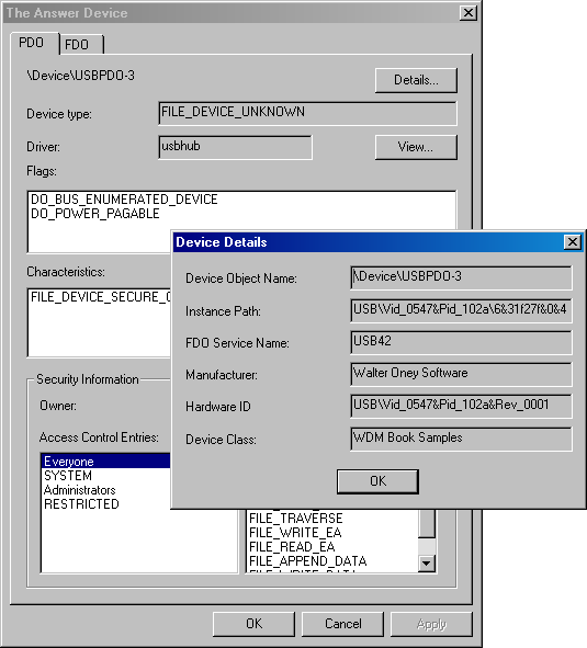
Figure 2-11. DEVVIEW information about USB42 s PDO.
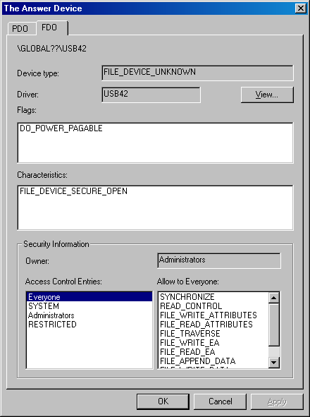
Figure 2-12. DEVVIEW information about USB42 s FDO.
EAN: 2147483647
Pages: 119