Selecting Objects
AutoCAD provides many options for selecting objects. This section has two parts : the first part covers object selection methods unique to AutoCAD, and the second part covers the more common selection method used in most popular graphic programs, the Noun/Verb method. Because these two methods play a major role in working with AutoCAD, it's a good idea to familiarize yourself with them early on.
| Tip | If you need to select objects by their characteristics rather than by their location, see Chapter 12, which describes the Quick Select and Object Selection Filters tools. These tools let you easily select a set of objects based on their properties, including object type, color , layer assignment, and so on. |
Selecting Objects in AutoCAD
Many AutoCAD commands prompt you to Select objects: . Along with this prompt, the cursor changes from crosshairs to a small square (look back at Figure 2.7). Whenever you see the Select objects: prompt and the square Object Selection cursor, you have several options while making your selection. Often, as you select objects on the screen, you will change your mind about a selection or accidentally pick an object you do not want. Let's take a look at most of the selection options available in AutoCAD, and learn what to do when you make the wrong selection.
Before you continue, you'll turn off two features that, while extremely useful, can be confusing to new users. These features are called Running Osnaps and Osnap Tracking. You'll get a chance to explore these features in depth later in this book, but for now use these steps to turn them off:
-
Check to see if either Running Osnaps or Osnap Tracking is turned on. Look at the Osnap and Otrack buttons in the status bar at the bottom of the AutoCAD window. If they are turned on, they look like they are pressed.

-
To turn off Running Osnap or Osnap Tracking, click the Osnap or Otrack button in the status bar. When turned off, they will look like they are not pressed.
Now let's go ahead and see how to select an object in AutoCAD:
-
 Choose Move from the Modify toolbar or type M
  .
. -
At the Select objects: prompt, click each of the two horizontal lines that constitute the door. As you know, whenever AutoCAD wants you to select objects, the cursor turns into the small square pickbox. This tells you that you are in Object Selection mode. As you pick an object, it is highlighted, as shown in Figure 2.11.
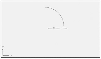
Figure 2.11: Selecting the lines of the door and seeing them highlighted -
After making your selections, you might decide to deselect some items. Enter U
from the keyboard. Notice that one line is no longer highlighted. When you type U , objects are deselected, one at a time, in reverse order of selection. -
You can deselect objects in another way. Hold down the Shift key and click the remaining highlighted line. It reverts to a solid line, showing you that it is no longer selected for editing.
-
By now you have deselected both lines. Let's try using another method for selecting groups of objects. To select objects with a selection window, type W
. The cursor changes to a Point Selection cursor, and the prompt changes to Specify First corner:
-
Click a point below and to the left of the rectangle representing the door. As you move your cursor across the screen, a selection window appears and stretches across the drawing area.
-
After the selection window completely encloses the door but not the arc, click this location to highlight the entire door. This window selects only objects that are completely enclosed by the window, as shown in Figure 2.12.
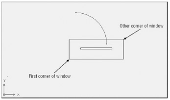
Figure 2.12: Selecting the door within a selection windowTip Don't confuse the selection window you are creating here with the zoom window you used in Chapter 1, which simply defines an area of the drawing you want to enlarge. Remember that the Window option works differently under the Zoom command than it does for other editing commands.
Warning If you are using a mouse you're not familiar with, it's quite easy to accidentally click the right mouse button when you really wanted to click the left mouse button, and vice versa. If you click the wrong button, you'll get the wrong results. On a two-button mouse, the right button will either act like the
key or open a context-sensitive shortcut menu, depending on your current operation. An will be issued if you are selecting objects, but otherwise the shortcut menu appears. -
Now that you have selected the entire door but not the arc, press
. This tells AutoCAD you have finished selecting objects. It is important to remember to press as soon as you finish selecting the objects you want to edit. A new prompt, Specify base point or displacement:, appears. The cursor changes to its Point Selection mode.
Now you have seen how the selection process works in AutoCAD ”but you're in the middle of the Move command. The next section discusses the prompt that's now on your screen and describes how to enter base points and displacement distances.
Providing Base Points
When you move or copy objects, AutoCAD prompts you for a base point, which is a difficult concept to grasp. AutoCAD must be told specifically from where and to where the move occurs. The base point is the exact location from which you determine the distance and direction of the move. After the base point is determined, you can tell AutoCAD where to move the object in relation to that point.
Follow these steps to practice using base points:
-
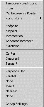
To select a base point, hold down the Shift key and right-click. A menu appears displaying the Object Snap (Osnap) options.
Warning When right-clicking the mouse, make sure the cursor is within the AutoCAD drawing area; otherwise, you will not get the results described in this book.
-
Choose Intersection from the Osnap menu. The Osnap menu closes .
-
Move the cursor to the lower-right corner of the door. Notice that as you approach the corner, a small x-shaped graphic appears on the corner. This is called an Osnap marker.
-
After the x-shaped marker appears, hold the mouse motionless for a second or two. A tool tip appears, telling you the current Osnap point AutoCAD has selected.
-
Now click the left mouse button to select the intersection indicated by the Osnap marker. Whenever you see the Osnap marker at the point you want to select, you don't have to point exactly at the location with your cursor. Just left-click the mouse to select the exact Osnap point (see Figure 2.13). In this case, you selected the exact intersection of two lines.
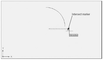
Figure 2.13: Using the Osnap cursor -
At the Specify second point of displacement or <use first point as displacement>: prompt, hold down the Shift key and click the right mouse button again. You'll use the Endpoint Osnap this time, but instead of clicking the option with the mouse, type E .
-
Now pick the lower-right end of the arc you drew earlier. (Remember that you only need to move your cursor close to the endpoint until the Osnap marker appears.) The door moves so that the corner of the door connects exactly with the endpoint of the arc (see Figure 2.14).
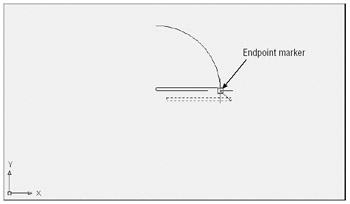
Figure 2.14: The rectangle in its new position after using the Endpoint Osnap
As you can see, the Osnap options enable you to select specific points on an object. You used Endpoint and Intersection in this exercise, but other options are available. Chapter 3 discusses some of the other Osnap options. You might have also noticed that the Osnap marker is different for each of the options you used. You'll learn more about Osnaps in Chapter 3. Now let's continue with our look at point selection.
| |
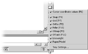
To the far right of the status bar, you'll see a downward-pointing arrow. This arrow opens a menu that controls the display of the status bar. You use this menu to turn the items in the status bar on or off. A check- mark by an item indicates that it is currently on. If for some reason you do not see all the buttons mentioned in the previous exercise, check this menu to make sure that all the status bar options are turned on. Note that LT does not have an Otrack option in the status bar.
| |
| Tip | You might have noticed the statement use first point as displacement in the prompt in step 6. This means that if you press |
If you want to specify an exact distance and direction by typing a value, select any point on the screen as a base point. Or you can just type @ followed by ![]() at the base point prompt; then enter the second point's location in relative coordinates. Remember that @ means the last point selected. In the next exercise, you'll try moving the entire door an exact distance of 1 unit in a 45 ° angle. Metric users will move the door 3 units in a 45 ° angle. Here are the steps:
at the base point prompt; then enter the second point's location in relative coordinates. Remember that @ means the last point selected. In the next exercise, you'll try moving the entire door an exact distance of 1 unit in a 45 ° angle. Metric users will move the door 3 units in a 45 ° angle. Here are the steps:
-
Click the Move tool on the Modify toolbar.
-
Type P
. The set of objects you selected in the previous exercise is highlighted. P is a selection option that selects the previously selected set of objects. -
You're still in Object Selection mode, so click the arc to include it in the set of selected objects. Now the entire door, including the arc, is highlighted.
-
Press
to tell AutoCAD that you have finished your selection. The cursor changes to Point Selection mode. -
At the Base point or displacement: prompt, choose a point on the screen between the door and the left side of the screen (see Figure 2.15).
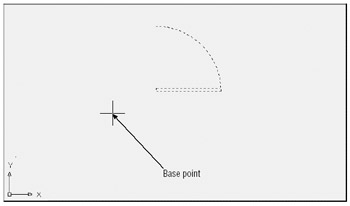
Figure 2.15: The highlighted door and the base point just to the left of the door. Note that the base point does not need to be on the object that you are moving. -
Move the cursor around slowly and notice that the door moves as if the base point you selected were attached to the door. The door moves with the cursor, at a fixed distance from it. This demonstrates how the base point relates to the objects you select.
-
Now type @1<45
. (Metric users should type @3<45 .) The door moves to a new location on the screen at a distance of 1 unit (or 3 for metric users) from its previous location and at an angle of 45 °. Tip If AutoCAD is waiting for a command, you can repeat the last command used by pressing the spacebar or by pressing
. You can also right-click in the drawing area and select the option at the top of the list. If you right-click the Command window, a shortcut menu offers the most recent commands.
This exercise illustrates that the base point does not have to be on the object you are manipulating; it can be virtually anywhere on your drawing. You also saw how to re-select a group of objects that were selected previously, without having to duplicate the selection process.
Using "Noun/Verb"Selection
Nearly all graphics programs today allow the Noun/Verb method for selecting objects. This method requires you to select objects before you issue a command to edit them ”that is, you identify the "noun" (the object you want to work on) before the "verb" (the action you want to perform on it). The exercises in this section show you how to use the Noun/Verb method in AutoCAD.
You have seen that when AutoCAD is waiting for a command, it displays the crosshair cursor with the small square. As mentioned before, this square is actually a pickbox superimposed on the cursor. It indicates that you can select objects, even while the command prompt appears at the bottom of the screen and no command is currently active. The square momentarily disappears when you are in a command that asks you to select points.
| |
There are several other selection options you haven't tried yet. You'll see how these options work in exercises later in this book. Or if you are adventurous, try them now on your own. To use these options, type their keyboard abbreviations (shown in brackets in the following list) at any Select object: prompt.
All [all
Crossing [c
Crossing Polygon [cp
Fence [f
Last [l
Multiple [m
Previous [p
Window [w
Window Polygon [wp
The following two selection options are also available, but seldom used. They are intended for use in creating custom menu options or custom toolbar tools.
Auto [au
Single [si
| |
| Tip | In addition to Noun/Verb selection, AutoCAD offers other selection options that enable you to use familiar GUI techniques. See Appendix B to learn how you can control object selection methods. This appendix also describes how to change the size of the standard cursor. |
Now try moving objects by first selecting them and then using the Move command:
-
Press the Esc key twice to make sure AutoCAD isn't in the middle of a command you might have accidentally issued. Then click the arc. The arc is highlighted, and you might also see squares appear at its endpoints and its midpoint . As stated earlier, these squares are called grips . You'll get a chance to work with them a bit later.
-
Choose Move from the Modify toolbar. The cursor changes to Point Selection mode. Notice that the grips on the arc disappear, but the arc is still selected.
-
At the Base point: prompt, pick any point on the screen. The prompt To point: appears.
-
Type @1<0
. Metric users should type @3<0 . The arc moves to a new location 1 unit (3 units for metric users) to the right. Warning If you find that this exercise does not work as described here, chances are the Noun/Verb setting has been turned off on your copy of AutoCAD. To turn on the Noun/Verb setting, choose Tools Options to open the Options dialog box, and click the Selection tab. In the Selection Modes group, turn on the Noun/Verb Selection option and click OK.
In this exercise, you picked the arc before issuing the Move command. Then, when you clicked the Move tool, you didn't see the Select object: prompt. Instead, AutoCAD assumed you wanted to move the arc that you selected and went directly to the Base point:[ prompt.
Using Autoselect
Next you will move the rest of the door in the same direction by using the Autoselect feature:
-
Pick a point just above and to the left of the rectangle representing the door. Be sure not to pick the door itself. A selection window appears that you can drag across the screen as you move the cursor. If you move the cursor to the left of the last point selected, the window appears dotted (see the first image of Figure 2.16). If you move the cursor to the right of that point, it appears solid (see the second image of Figure 2.16).
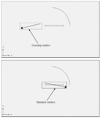
Figure 2.16: The dotted window (first image) indicates a crossing selection; the solid window (second image) indicates a standard selection window. -
Pick a point below and to the right of the door so that the door is completely enclosed by the window, as shown in the bottom image in Figure 2.16. The door is highlighted (and again, you might see grips appear at the line's endpoints and midpoints).
-
Click the Move tool again. Just as in the preceding exercise, the Base point: prompt appears.
-
Pick any point on the screen; then enter @1<0
. Metric users should enter @3<0 . The door joins with the arc.
The two selection windows you have just seen ”the solid one and the dotted one ”represent a standard window and a crossing window. If you use a standard window, anything that is completely contained within the window is selected. If you use a crossing window, anything that crosses through the window is selected. These two types of windows start automatically when you click any blank portion of the drawing area with a Standard cursor or Point Selection cursor; hence the name Autoselect.
Next, you will select objects with an automatic crossing window:
-
Pick a point below and to the right of the door. As you move the cursor left, the crossing (dotted) window appears.
-
Select the next point so that the window encloses the door and part of the arc (see Figure 2.17). The entire door, including the arc, is highlighted.
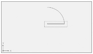
Figure 2.17: The door enclosed by a crossing window -
Click the Move tool.
-
Pick any point on the screen; then enter @1<180
. Metric users should type @3<180 . The door moves back to its original location.
You'll find that in most cases, the Autoselect standard and crossing windows are all you need when selecting objects. They really save you time, so you'll want to become familiar with these features.
Before continuing, you need to choose File Save to save the Door file. You won't want to save the changes you make in the next section, so saving now stores the current condition of the file on your hard disk for safekeeping.
Restrictions on Noun/Verb Object Selection
If you prefer to work with the Noun/Verb selection feature, you should know that its use is limited to the following subset of AutoCAD commands, listed here in alphabetic order:
| Array | Copy | Hatch | Rotate |
| Block | Dview | List | Scale |
| Change | Erase | Mirror | Stretch |
| Chprop | Explode | Move | Wblock |
For all other modifying or construction-oriented commands, the Noun/Verb selection method is inappropriate because for those commands you must select more than one set of objects. But you do not need to remember this list. You'll know whether a command accepts the Noun/Verb selection method right away. Commands that don't accept the Noun/Verb selection method clear the selection and then display a Select object: prompt.
If you want to take a break, now is a good time to do it. If you want, exit AutoCAD and return to this point in the tutorial later. When you return, start AutoCAD and open the Door file.
EAN: 2147483647
Pages: 261