Fine-Tuning the Appearance of Output
In Chapter 7, you were introduced to the printing and plotting features in AutoCAD. You learned about the different AutoCAD features you can use to control the appearance of your output including layouts and lineweights. This section covers some of the finer points of printer and plotter setup. You'll find information on controlling how lines overlap, how to include more media sizes, adding plot stamps, adjusting the aspect ratio or your printer and more.
Making Detailed Adjustments with the Printer/Plotter Configuration Options
If you open the Plot dialog box or the Page Setup dialog box, you'll see the option groups that offer control over how your plotter or printer works.
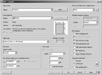
These groups seem innocent enough, but behind two of these groups lies a vast set of options that can be quite intimidating. You've already seen in Chapter 7 how the Plot Style Table options work. This section covers the options available when you click the Properties button in the Printer/Plotter group .
The Printer/Plotter Configuration options enable you to adjust those printer or plotter settings that you might want to change only occasionally. These settings are fairly technical and include such items as the port your printer is connected to, the quality of bitmap image printing, custom paper sizes, and printer calibration, which lets you adjust your plotter for any size discrepancies in output. You won't be using most of these settings often, but you should know that they exist just in case you encounter a situation in which you need to make some subtle change to your printer's configuration. You can also use these options to create multiple configurations of the same plotter for quick access to custom settings.
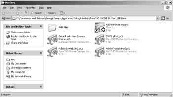
All the settings in this group are stored in a file with the .pc3 filename extension. You can store and recall any number of configuration files for situations that call for different plotter settings. PC3 files are normally stored in the Plotters folder under the C:\Documents and Settings\ User Name \ Application Data\Autodesk\AutoCAD 2005\R16.1\enu\ folder. User Name is your login name. You can access this folder by choosing File Plotter Manager from the AutoCAD menu bar.
The Printer/Plotter group in the Plot And Page Setup dialog box offers a drop-down list from which you can select a printer or file output configuration. If a PC3 file exists for a plotter configuration, the drop-down list will display it, and the list will display any Windows system printer. After you've selected an output device from the list, you can click the Properties button to access the Plotter Configuration Editor dialog box.
| Tip | You can configure AutoCAD to create bitmap files in the most common file formats (such as TIFF, Targa, and PCX) or to create Autodesk's DWF file format for the Internet. After you've configured AutoCAD for these types of output, this is where you select the file output type. |
The Plotter Configuration Editor dialog box has three tabs. The General tab displays a list of Windows drivers that this configuration uses, if any, and there is a space for your own comments.
| Tip | You can access and edit the plotter configuration settings without opening AutoCAD. To do this, locate the PC3 file in the Plotters subdirectory under the C:\Documents and Settings\User Name\Application Data\Autodesk\AutoCAD 2005\R16.1\enu\Plotters directory (where User Name is your login name), and double-click it. |
The Ports tab lets you specify where your plotter data is sent. This is where you should look if you are sending your plots to a network plotter or if you decide to create plot files. You can also select the AutoSpool feature, which enables you to direct your plot to an intermediate location for distribution to the appropriate output device.
The Device And Document Settings tab is the main part of this dialog box. It offers a set of options ranging from OLE output control to custom paper sizes. The main list box offers options in a hierarchical list, similar to a listing in Windows Explorer. Toward the bottom of the dialog box are the Import, Save As, and Defaults buttons. These buttons let you import configuration settings from earlier versions of AutoCAD, save the current settings as a file, or return the settings to their default values.
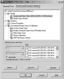
The list has four main categories: Media, Graphics, Custom Properties, and User-Defined Paper Sizes & Calibration. Not all the options under these categories are available for all plotters. When you select an item from this list, the area just below the list displays the options associated with that item. The following describes each category and its options, using the Xerox Engineering Systems XES8855 as an example.
The Media Category
Some plotters, such as the Xerox Engineering Systems 8800 series, offer options for the source and size of printer media and for the media type. If the Source And Size option is available, the dialog box offers a listing of the source, such as sheet feed or roll, and the sheet size. The Media Type option lets you choose from bond, vellum, or glossy paper or any other medium that is specifically controlled by the plotter. Duplex Printing, when available, controls options for double-sided printing in printers that support this feature. Media Destination, when available, lets you select a destination for output such as collating or stapling in printers that support such features.
The Physical Pen Configuration Category (Shown Only for Pen Plotters)
Pen plotters have features that diverge from the typical laser or ink-jet printer or plotter. When these options are present, they let you control some of the ways that AutoCAD generates data for pen plotters. Here is a listing of those pen plotter feature settings:
Prompt For Pen Swapping Stops the plotter to enable you to switch pens. This feature is designed primarily for single-pen plotters.
Area Fill Correction Tells AutoCAD to compensate for pen width around the edges of a solid- filled area in order to maintain dimensional accuracy of the plot.
Pen Optimization Level Sets how AutoCAD sorts pen movement for optimum speed. AutoCAD does a lot of preparation before sending your drawing to the plotter. If you are using a pen plotter, one of the things it does is optimize the way it sends vectors to your plotter, so your plotter doesn't waste time making frequent pen changes and moving from one end of the plot to another just to draw a single line.
Physical Pen Characteristics Lets you assign plotter pen numbers to AutoCAD colors, adjust the speed of individual pens, and assign pen widths.
The Graphics Category
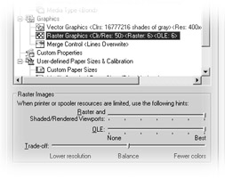
These settings give you control over both vector and raster output from your plotter. The Vector Graphics settings let you control resolution and color depth, as well as the method for creating shading. If you want to configure your printer for virtual pens, select 255 Virtual Pens under the Color Depth option.
The Raster and Shaded/Rendered Viewports settings slider gives you control over the quality of any bitmap images. If this setting is placed all the way to the left, raster images will not be plotted. As you move the slider to the right, the raster image quality increases , the speed of printing decreases, and memory requirements increase. The OLE Settings slider controls the quality of OLE linked or embedded files. With the slider all the way to the left, OLE objects will not be printed. As you move the slider farther to the right, OLE image quality and memory requirements increase while speed is reduced.
The Trade-off slider lets you choose how the Raster and OLE sliders improve speed. You can choose between lower resolution and fewer colors.
For printers and plotters that support TrueType fonts, the TrueType Text options enable you to select between plotting text as graphics or as TrueType text.
Custom Properties
Clicking the Custom Properties button gives you access to the same printer or plotter settings that are available from the Windows system printer settings. You can also access these settings by choosing Start Settings Printers, right-clicking the desired printer, and choosing Properties from the shortcut menu.
| Tip | The options offered through the Custom Properties button often duplicate many of the items in the Device And Documents list. If an option is not accessible from the Device And Documents list, select the options offered under Custom Properties. |
Initialization String
Some plotters require preinitialization and postinitialization codes, in the form of ASCII text strings, to get the plotter's attention. If you have such a plotter, this option lets you enter those strings.
User-Defined Paper Sizes & Calibration
The options in the User-Defined Paper Sizes & Calibration category offer some of the more valuable options in this dialog box. In particular, the calibration option can be useful in ensuring the accuracy of your plots.
Plotter Calibration
If your printer or plotter is not producing an accurate plot, you should focus on the calibration option. If your plotter stretches or shrinks your image in one direction or another, the calibration option lets you adjust the width and height of your plotter's output. To use it, click the Plotter Calibration listing under User-Defined Paper Sizes & Calibration.
A button appears labeled Calibrate Plotter. Click this button to start the Calibrate Plotter Wizard. You are asked first to select a paper size, and then to select a width and height for a rectangle that will be plotted with your printer. Figure B.1 shows the wizard screen that asks for the rectangle size.
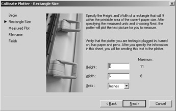
Figure B.1: The Calibrate Plotter Wizard lets you adjust the width and height scaling of your plotter output in order to fine-tune the accuracy of your plots.
You can use the Calibrate Plotter Wizard to plot a sample rectangle of a specific size. You then measure the rectangle and check its actual dimensions against the dimensions that you entered. If there are any discrepancies between the plotted dimensions and the dimensions you specified, you can enter the actual plotted size and print another test rectangle. You can repeat this process until your plotted rectangle exactly matches the dimensions entered into the wizard.
Toward the end of the Calibrate Plotter Wizard's steps, you'll be asked to give a name for a Plot Model Parameter (PMP) file that will store your calibration data. The PMP file also stores any custom paper size information that you input from other parts of the User-Defined Paper Sizes & Calibration options. This file is then associated with the PC3 file that stores your plotter configuration data.
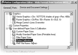
If you have more than one PC3 file for your plotter, you can associate the PMP file with your other PC3 files by using the PMP File Name option in the Device And Document Settings list box. You need only one calibration file for each plotter or printer you are using. This option appears under the User-Defined Paper Sizes & Calibration category.
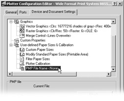
To associate a PMP file with a PC3 plotter configuration file, select the PC3 file from the Name drop-down list in the Plot Device tab in the Plot dialog box. Click the Properties button and then, in the Device And Document Settings tab, click the PMP File Name listing. The PMP options appear in the bottom of the dialog box. Click the Attach button, and then select the PMP file from the Open dialog box. Click OK. You'll see that the PMP file has been added to the PMP filename listing.
Custom Paper Sizes
Some plotters offer custom paper sizes. This feature is usually available for printers and plotters that you've set up to use the AutoCAD drivers instead of the Windows system drivers. If your plotter offers this option, you'll see a list box and a set of buttons when you select Custom Paper Sizes.
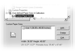
Clicking the Add button starts the Custom Paper Size Wizard, which lets you set the sheet size and margin, as well as the paper source. This information is then saved in a PMP file. You are asked to provide a specific name for the custom paper size, which will be listed in the Custom Paper Size list box.
After you've created a custom paper size, you can edit or delete it by using the Edit or Delete button in the Custom Paper Size options.
Modify Standard Paper Size
The last item in the Device And Document Settings list is the Modify Standard Paper Size option. If this option is available, it enables you to adjust the margins of a standard paper size.
| Tip | If you are using an older pen plotter, you will see the Physical Pen Configuration options in the Device And Document Settings list box. These additional options give you control over pen speed, pen optimization, and area fill correction. |
Import, Save As, and Defaults
The Import, Save As, and Defaults buttons at the bottom of the Plotter Configuration Editor let you import or save your plotter settings as PC3 files, which you can then load from the Plot Device tab of the Plot dialog box and the Page Setup dialog box, as described earlier in this appendix. The Import button lets you import PCP and PC2 files from earlier versions of AutoCAD. Save As lets you save your current settings under an existing or a new PC3 filename. The Defaults button restores the default settings, if any, for the current plotter configuration.
Adding a Plot Stamp
To help cross-reference your printer or plotter output to AutoCAD drawing files, it's a good idea to add a plot stamp to your drawings that identifies the date, the time, and the filename of the drawing that generated your plot. To accomplish this, the Plot Stamp feature lets you imprint data onto your plotted drawings, usually in the lower-left corner. In addition, Plot Stamp lets you keep a record of your plots in a log file.
To use Plot Stamp, type Plotstamp ![]() at the AutoCAD command prompt. You can also turn on the Plot Stamp option in the Plot dialog box and then click the Plot Stamp Setting button that appears to the right of the option. The Plot Stamp dialog box opens (see Figure B.2).
at the AutoCAD command prompt. You can also turn on the Plot Stamp option in the Plot dialog box and then click the Plot Stamp Setting button that appears to the right of the option. The Plot Stamp dialog box opens (see Figure B.2).
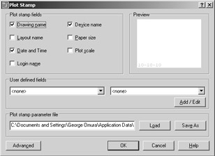
Figure B.2: The Plot Stamp dialog box
The Plot Stamp dialog box offers several options that let you determine what to include in the stamp.
| Tip | If the options are grayed out, click the Save As button to save Plot Stamp settings under a new file. |
The Plot Stamp Fields group lets you include seven predefined options in your stamp, including drawing, layout, and output device name. The User Defined Fields group lets you add custom text to the stamp. To use this feature, click the Add/Edit button in the User Defined Fields group. The User Defined Fields dialog box appears, as shown in Figure B.3.
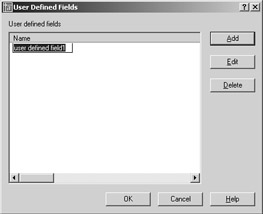
Figure B.3: The User Defined Fields dialog box
You can use the Add, Edit, or Delete button to add or make changes to the user-defined fields. After you've added a field, it will appear in both of the list boxes in the User Defined Fields group of the Plot Stamp dialog box.
To control the location, orientation, font, and font size of the plot stamp, you can click the Advanced button in the lower-left corner of the Plot Stamp dialog box. This opens the Advanced Options dialog box, shown in Figure B.4.
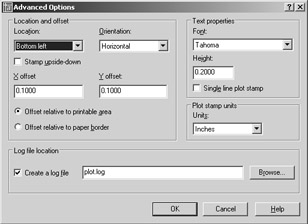
Figure B.4: The Advanced Options dialog box
This dialog box lets you specify the orientation of the stamp on the page as well as the exact location of the stamp in relation to either the printable area or the paper border. In addition, you can specify whether to save a record of your plotting activities in a log file by using the Log File Location group.
Using Merge Control
Some output devices let you control how overlapping lines and shaded areas affect each other, a feature known as merge control. In versions of AutoCAD prior to 2000, merge control was handled through additional commands such as Hpconfig or OCEconfig. AutoCAD 2005 includes merge control as part of the Plotter Configuration Editor dialog box.
You can gain access to merge control by opening the Plotter Configuration Editor and, in the Graphics And Document Settings list box, clicking the plus sign next to Graphics to expand the list of Graphics options.
If your device supports merge control, you will see it listed under Graphics as shown in Figure B.5.
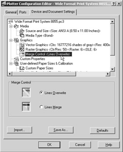
Figure B.5: The location of the Merge Control setting in the Plotter Configuration Editor
Filtering Paper Sizes
AutoCAD displays all the available paper sizes for a selected output device in the Page Setup dialog box or the Plot dialog box. For some plotters, the list can be a bit overwhelming. You can filter out paper sizes that you do not need by using the Filter Paper Sizes option in the Plotter Configuration Editor.
Open the Plotter Configuration Editor and click the plus sign next to the User-Defined Paper Sizes & Calibration listing. You'll see Filter Paper Sizes as an option. After you select this option, you'll see the Filter Paper Sizes area in the lower half of the Plotter Configuration Editor. Remove the checkmark in the box next to any size you won't need.
Filtering Printers
In some instances, you might want to hide the Windows system printer from the list of printers shown in the AutoCAD Plot dialog box. For example, there might be several shared system printers on a network that are not intended for AutoCAD use, so you would not want those printers to appear in your list of available printers. You can do this by turning on the Hide System Printers option at the bottom of the General Plot Options group in the Plot And Publish tab of the Options dialog box (choose Tools Options). This limits the selection of printers and plotters to those that have a PC3 plotter configuration. You can further limit the plotter selections by moving any unneeded PC3 file out of the AutoCAD Plotters folder and into another folder for storage.
Controlling the Plot Preview Background Color
If you prefer to use a color other than white for the plot preview background, you can set the plot preview background color by using the Color Options dialog box:
-
Choose Tools Options to open the Options dialog box.
-
Select the Display tab.
-
In the Windows Elements group, click the Color button to open the Color Options dialog box.
-
Select Plot Preview Background from the Window Element drop-down list.
-
Select a color from the Color drop-down list.
-
Click the Apply & Close button.
Controlling the Windows Metafile Background Color
If you prefer using the Windows metafile file type to export AutoCAD drawings to other programs, you can now control the background color of your exported file. The AutoCAD Wmfbkgnd system variable lets you control the background color of exported Windows metafiles. Wmfbkgnd offers two settings: off generates a transparent background, and on generates the background color of the current view. The initial default value is off.
EAN: 2147483647
Pages: 261